6 minute read
Turbochargers


OIL FILTER HOUSING
10. Install O-ring seals (15) on housing (4) and put clean engine oil on the seals.
Advertisement
11. Put the O-ring seal, spring (17) and retainer (16) in position on cover (18).
12. Install ring (19) to hold the retainer and spring in position. Install O-ring seal (20) on cover (18) and put clean engine oil on it.
13. Install three element assemblies (21) in housing assembly (13). Install cover (18) on housing assembly (13).
end by: a) install oil filter housing
299
OIL PAN
REMOVE OIL PAN 1302-11
1. Drain the oil from the engine.
2. Remove bolts (1) that hold the oil pump adapter to the oil pan.
3. Remove the bolts that hold oil pan (2) to the engine and lift the engine off of the oil pan or lower the oil pan away from the engine. The weight of the 3512 oil pan is 295 kg (650 lb.) and the weight of the 3508 oil pan is 240 kg (530 lb.). The weight of the 3512 engine is approximately 5443 kg (12, 000 lb.) and the weight of the 3508 engine is approximately 4445 kg (9800 lb.).
INSTALL OIL PAN 1302-12
1. Make sure the O-ring seal is installed on the oil pump adapter and put clean engine oil on it.
2. Install four 3/8"-16 NC guide bolts in the pan and put the oil pan gasket in position on the pan.
3. Put the engine in position on the oil pan or put oil pan (1) in position under the engine. Install the bolts that hold the oil pan to the engine.
4. Install bolts (2) that hold the oil pump adapter to the oil pan. 5. Fill the engine with oil to the correct level.
300
OIL PAN
DISASSEMBLE OIL PAN 1302-15
start by: a) remove oil pan
1. Remove covers (1), (2) and the O-ring seals.
2. Remove screen assembly (3) from the oil pan. Remove O-ring seals from the screen assembly.
3. Remove the bolts and remove oil level gauge (4) from the oil pan.
4. Remove the bolts that hold bell (5) to the oil pan. Pull bell (5) off the O-ring seals on the end of the tube assembly and remove bell (5) from the oil pan.
301
OIL PAN
5. Pull tube assembly (7) from housing (6). Remove the bolts that hold housing (6) in position and remove it from the oil pan. Remove the 0ring seals from the oil pan.
6. Remove tube assembly (7) from the oil pan. Remove the O-ring seals from tube assembly (7).
Assemble Oil Pan 1302-16
1. Install the O-ring seals on the ends of tube assembly (1) and put clean engine oil on the seals. Install tube assembly (1) in the oil pan.
2. Install the O-ring seal in the top of housing (2) and put clean engine oil on it. Put housing (2) in position and install the bolts to hold it in position.
302
OIL PAN
3. Push tube assembly (1) into housing (2).
4. Put bell (3) in position over the end of tube assembly (1) and install the bolts to hold it to the oil pan.
5. Install oil level gauge (4) and the gasket in the oil pan. Install the bolts to hold the gauge in position.
6. Install the O-ring seals on screen assembly (7) and put clean engine oil on the seals. Install screen assembly (7) in the oil pan.
7. Install the O-ring seals on covers (5), (6) and put clean engine oil on the seals. Install covers (5) and (6) on the front of the oil pan. end by: a) install oil pan
303
OIL SEQUENCE VALVES
REMOVE AND INSTALL OIL SEQUENCE VALVES
start by: a) remove front drive housing b) remove flywheel housing
1. Remove cover (1) from the front of the cylinder block.
2. Remove plunger assembly (2) and spring (3) from the front of the cylinder block.
3. Remove the gear assembly, idler gear and shaft from over cover (4) on the rear of the cylinder block.
4. Remove cover (4) from the rear of the cylinder block.
5. Remove plunger assembly (5) and spring (6) from the rear of the cylinder block.
6. Put clean engine oil on spring (6) and plunger assembly (5) and install them as shown in the rear of the cylinder block.
7. Install cover (4). Install the idler gear, shaft and gear assembly over cover (4) on the rear of the cylinder block.
8. Put clean engine oil on spring (3) and plunger assembly (2) and install them in the front of the cylinder block as shown.
9. Install cover (I) to hold the plunger assembly and spring in position. end by: a) install flywheel housing b) install front drive housing
304
OIL COOLER
REMOVE OIL COOLER 1378-11
1. Drain the coolant from the cooling system.
2. Drain the oil from the oil cooler.
3. Remove the bolt and remove clips (1) from oil tube (2).
4. Disconnect oil hose (3) from elbow (4).
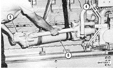
5. Remove the bolts and retainers that hold oil tube (2) to elbow (4) and pull tube (2) out of elbow (4). Remove the bolts and remove elbow (4) from the oil cooler.
6. Remove the bolts to disconnect flange (5) and tube (6) from the water line adapter.
NOTE: Step 7 is for the 3512 Engines.
7. Remove the bolts from elbow (7) and remove elbow (7) and tube (8) as a unit from the oil cooler bonnet.
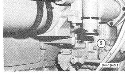
8. Fasten a hoist to the oil cooler and remove the bolts from bracket (9).
3512 ENGINES
305
OIL COOLER
NOTE: Step 9 is for the 3512 Engine.
9. Deleted.
NOTE: Step 10 is for the 3508 Engine.
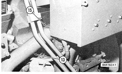
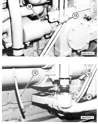
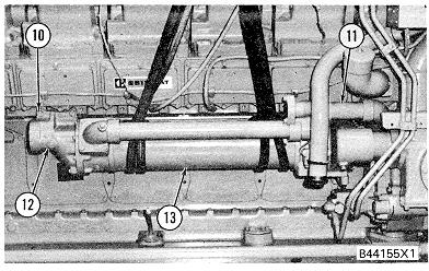
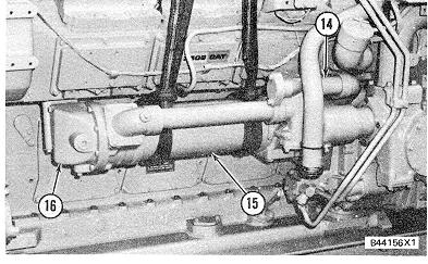
10. Remove the four bolts from bonnet (16) and pull oil cooler (15) from oil tube (14). Remove the cooler from the engine. The weight of cooler (15) is 50 kg (110 lb.).
INSTALL OIL COOLER 1378-12
NOTE: Step I is for the 3508 Engine.
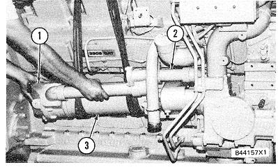
1. Put clean engine oil on the O-ring seal on oil tube (2). Fasten a hoist to oil cooler (3) and put cooler (3) in position on oil tube (2). Make sure the gasket is in place and install the four bolts in bonnet (1) to hold the cooler in position.
NOTE: Step 2 is for the 3512 Engine.
2. Put clean engine oil on the O-ring seal on oil tube (4). Fasten a hoist to oil cooler (6) and put cooler (6) in position on oil tube (4). Install the two bolts in bonnet (5) to hold the cooler in position.
306
3512 ENGINES
3512 ENGINES
3508 ENGINES
3508 ENGINES
OIL COOLER
3. Install the bolts that hold the oil cooler to bracket (7) and remove the hoist from the oil cooler.
NOTE: Step 4 is for the 3512 Engine.
4. Deleted.
5. Make sure the gasket is in place and install the bolts to hold flange (I I ) and tube (10) to the water line adapter.
6. Put clean engine oil on the O-ring seal on elbow (14). Put elbow (14) in position on the oil cooler and install the bolts to hold it.
7. Put clean engine oil on the O-ring seal on the end of tube (13). Put tube (13) in position in elbow (14) and install the retainers and bolts to hold the tube.
8. Connect oil hose (12) to elbow (14).
9. Put clips (15) in position on tube (13) and install the bolt to hold the clips in position.