
4 minute read
Flywheel and Flywheel Housing


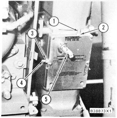
WOODWARD UG8 LEVER GOVERNOR
COMPENSATING ADJUSTMENT
Although the governor may appear to be operating satisfactorily at no load, high overspeeds and underspeeds after load changes and slow return to normal speed are the results of incorrect compensation adjustments.
After the temperature of the engine and the oil in the governor have reached normal operating values, make compensation adjustments with the engine running at no load conditions.
UG8 LEVER GOVERNOR 1. Compensation pointer. 2. Nut. 3. Plug.
1. Loosen nut (2) that holds compensation pointer (1) and move the pointer up as far as it will go. Tighten the nut.
2. Remove plug (3) from the base of the governor to get access to the needle valve.
3. Use a screwdriver and turn the needle valve three to five turns in a counterclockwise (open) direction. Make sure the screwdriver engages with the shallow slot of the compensating needle valve and not in the deep slot that is at right angles to the shallow screwdriver slot.
4. Let the engine surge for approximately 30 seconds to help remove air from the governor oil passages.
5. Loosen nut (2) that holds compensation pointer (1) and move the pointer down as far as it will go. Tighten the nut. 6. Slowly turn the needle valve in a clockwise direction until the engine surge just stops.
7. Now check the number of turns the needle valve is open. To find the number of turns the needle valve is open, close the valve completely and make a note of the number of turns needed to close the valve.
8. Open the needle valve to the same position at which the engine did not surge (Step 6).
9. Move the governor linkage to change the engine speed. If the engine does not surge, and the needle valve is 1/2 to 3/4 of a turn open, the governor adjustment is correct. Install plug (3) in the base. If the needle valve is more than 3/4 of a turn open, do the steps that follow.
10. Loosen nut (2) and move compensation pointer (1) up two marks on the pointer scale.
11. Turn the needle valve three to five turns in a counterclockwise direction.
12. Let the engine surge for approximately 30 seconds to help remove air from the governor oil passages.
13. Slowly turn the needle valve in a clockwise direction until the engine surge just stops.
14. Now check the number of turns the needle valve is open. To find the number of turns the needle valve is open, close the valve completely and make a note of the number of turns needed to close the valve.
15. Open the needle valve to the same position at which the engine did not surge (Step 13).
16. Move the governor linkage to change the engine speed. If the engine does not surge, and the needle valve is 1/2 to 3/4 of a turn open, the governor adjustment is correct. Install plug (3) in the base. If the needle valve is more than 3/4 of a turn open, do Steps 10 thru 16 again.
A needle valve that is opened less than 1/2 turn will cause a slow return of the engine to normal speed after a load change.
If the compensation pointer is too far toward the maximum position, the engine speed change will be too great when the load changes.
128
LOW AND HIGH IDLE SPEED ADJUSTMENT
Connect a tachometer with good accuracy to the engine. Make reference to MEASURING ENGINE SPEED.
1. Start the engine and run to get the engine to the normal temperature of operation.
LOW AND HIGH IDLE ADJUSTMENT 1. Low idle adjustment screw. 2. Locknut. 3. Locknut. 4. High idle adjustment screw. 5. Governor speed adjustment shaft.
2. Move the governor speed adjusting shaft (5) to run the engine at high idle speed. Loosen locknut (3) and turn high idle adjustment screw (4). Turn adjustment screw (4) clockwise to decrease engine speed and counterclockwise to increase engine speed.
3. After the high idle speed has been adjusted, tighten the locknut and check high idle speed again.
NOTE: Make reference to the Fuel Setting Information Fiche for the correct low and high idle speed.
4. Move the governor speed adjusting shaft (5) to run the engine at low idle speed. Loosen locknut (2) and turn low idle adjustment screw ( I ). Turn adjustment screw ( I ) clockwise to increase low idle speed and counterclockwise to decrease low idle speed. LOW AND HIGH IDLE STOP LEVER 6. Low and high idle stop lever.

SPEED DROOP ADJUSTMENT
Adjustment for Zero Droop
Tools Needed: 8S2328 Dial Indicator Group. 5P7264 Indicator Contact Point Group.
1. Disconnect the engine oil pressure and air inlet pressure lines for the air fuel ratio control housing.

COVER AND SHUT-OFF SOLENOID 1. Cover assembly.
2. Remove the oil level gauge from cover assembly (1).


