4 minute read
Starting System Air Starting System...................................Deleted


EXHAUST TEMPERATURE
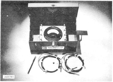
1P3060 PYROMETER GROUP
Use the IP3060 Pyrometer Group to check exhaust temperature. Special Instruction, Form No. SMHS7179 is with the tool group and gives instructions for the test procedure.
CRANKCASE (CRANKSHAFT COMPARTMENT) PRESSURE
Pistons or rings that have damage can be the cause of too much pressure in the crankcase. This condition will cause the engine to run rough. There will also be more than the normal amount of fumes coming from the crankcase breather. This crankcase pressure can also cause the element for the crankcase breather to have a restriction in a very short time. It can also be the cause of oil leakage at gaskets and seals that would not normally have leakage.
COMPRESSION
An engine that runs rough can have a leak at the valves, or have valves that need adjustment. Removal of the head and inspection of the valves and valve seats is necessary to find those small defects that do not normally cause a problem. Repair of these problems is normally done when reconditioning the engine.
CYLINDER HEADS
The cylinder heads have valve seat inserts, valve guides and bridge dowels that can be removed when they are worn or have damage. Replacement of these components can be made with the tools that follow.
Valves
Valve removal and installation is easier with use of the IP3527 Valve Spring Compressor Assembly.
Valve Seat Inserts
To remove and install valve seat inserts, use the 6V4805 Valve Seat Extractor Group. For installation, lower the temperature of the insert before it is installed in the head.
Valve Guides
Tools needed to remove and install valve guides are the 5P1729 Bushing and 7M3975 Driver. The counterbore in the driver bushing installs the guide to the correct height. Use a I P7451 Valve Guide Honing Group to make a finished bore in the valve guide after installation of the guide in the head. Special Instruction, Form No. SMHS7526 gives an explanation for this procedure. Grind the valves after the new valve guides are installed.
Checking Valve Guide Bores
Use the 5P3536 Valve Guide Gauge Group to check the bore of the valve guides. Special Instruction, Form No. GMG02562 gives complete and detailed instructions for use of the 5P3536 Valve Guide Gauge Group.

SP3536 VALVE GUIDE GAUGE GROUP
134
Bridge Dowels
Use a 5P944 Dowel Puller Group with a 5P942 Extractor to remove the bridge dowels. Install a new bridge dowel with a 6V4009 Dowel Driver. This dowel driver installs the bridge dowel to the correct height.
BRIDGE ADJUSTMENT
When the cylinder head is disassembled, keep the bridges with their respective valves. To make an adjustment to the bridges, use the procedure that follows:
NOTE: The only time bridge adjustment is necessary is when a valve has been replaced, ground, or cylinder head has been reconditioned. Valves must be fully closed when adjustment is made. To find when valves are fully closed, see subject FINDING TOP CENTER POSITION FOR NO. 1 PISTON and chart CRANKSHAFT POSITIONS FOR INJECTOR TIMING AND VALVE CLEARANCE SETTING.
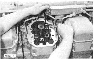
1. Put engine oil on bridge dowel (4) in the cylinder head and in the bore in bridge (2).
2. Install bridge (2) with adjustment screw (5) toward the exhaust manifold.

BRIDGE INSTALLATION 1. Top contact surface. 2. Bridge. 3. Valve stem. 4. Bridge dowel.
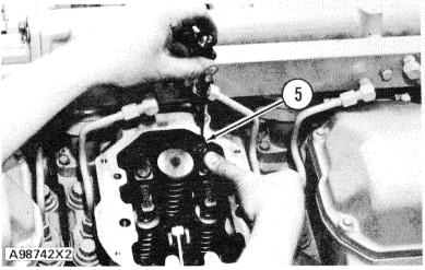
3. Loosen the locknut for adjustment screw (5) and loosen the adjustment screw several turns.
4. Put a force of 5 to 45 N (I to 10 lb.) by hand straight down on top contact surface (I ) of bridge (2). 5. Turn adjustment screw (5) clockwise until it just makes contact with valve stem (3). Then turn the adjustment screw 20 to 300 more in a clockwise direction to make the bridge straight on the dowel, and to make compensation for the clearance in the threads of the adjustment screw.
BRIDGE ADJUSTMENT 5. Adjustment screw.
6. Hold adjustment screw (5) in this position and tighten the locknut to 30 ± 4 N m (22 ± 3 lb. ft.).
TIGHTEN LOCKNUT
7. Put engine oil on top contact surface (I) where the rocker arm makes contact with the bridge.
135
CRANKSHAFT POSITIONS FOR FUEL TIMING AND VALVE CLEARANCE SETTING
STANDARD ROTATION (COUNTERCLOCKWISE) as Viewed From Flywheel End
ENGINE CORRECT STROKE FOR NO. PISTON AT TOP CENTER POSITION* CYLINDERS TO CHECK/ADJUST
VALVES INJECTORS
INTAKE EXHAUST
3508 COMPRESSION EXHAUST 3512 COMPRESSION EXHAUST 3516 COMPRESSION EXHAUST 1-2-6-8 3-5-4-7 1-3-6-7-10-12 2-4-5-8-9-11 1-2-5-7-8-12-13-14 3-4-6-9-10-11-15-16 1-2-3-7 4-5-6-8 1-4-5-6-9-12 2-3-7-8-10-11 1-2-3-4-5-6-8-9 7-10-11-12-13-14-15-16 3-4-5-7 1-2-6-8 2-4-5-8-9-11 1-3-6-7-10-12 3-4-6-9-10-11-15-16 1-2-5-7-8-12-13-14
ENGINE CORRECT STROKE FOR NO.1 PISTON AT TOP CENTER POSITION*
3508 COMPRESSION EXHAUST 3512 COMPRESSION EXHAUST 3516 COMPRESSION EXHAUST
REVERSE ROTATION (CLOCKWISE) - as Viewed From Flywheel End CYLINDERS TO CHECK/ADJUST
VALVES INJECTORS
INTAKE EXHAUST
1-3-4-8 2-5-6-7 1-3-4-6-7-12 2-5-8-9-10-11 1-2-5-6-7-8-13-14 3-4-9-10-11-12-15-16 1-2-7-8 3-4-5-6 1-4-5-8-9-12 2-3-6-7-10-11 1-2-3-4-5-6-9-10 7-8-11-12-13-14-15-16 2-5-6-7 1-3-4-8 2-5-8-9-10-11 1-3-4-6-7-12 3-4-9-10-11-12-15-16 1-2-5-6-7-8-13-14
*Put No. 1 piston at top center (TC) position and make identification for the correct stroke. Make reference to FINDING TOP CENTER POSITION FOR NO. 1 PISTON. After top center position for a particular stroke is found and adjustments are made for the correct cylinders, re- move the timing bolt and turn the flywheel 360° in the direction of normal engine rotation. This will put No. 1 piston at top center (TC) position on the other stroke. Install the timing bolt in the flywheel and complete the adjustments of the cylinders that remain.
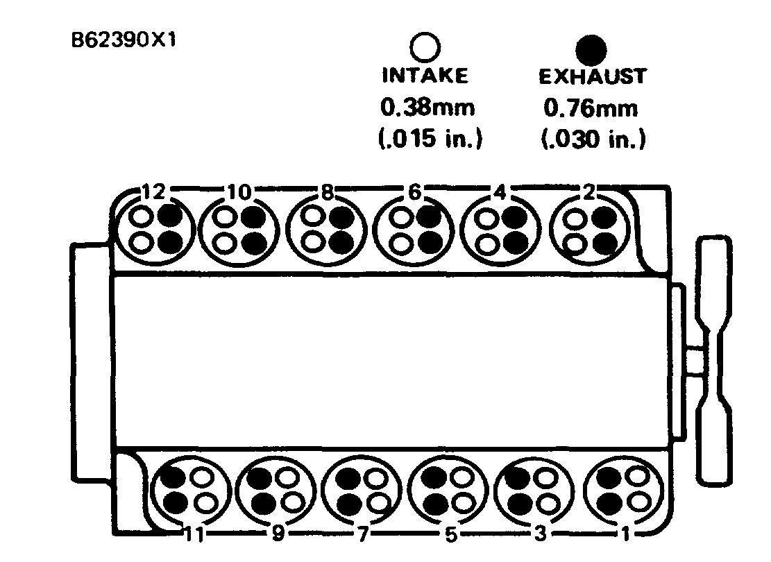
CYLINDER AND VALVE LOCATION (3512 SHOWN)


