3 minute read
Fuel System


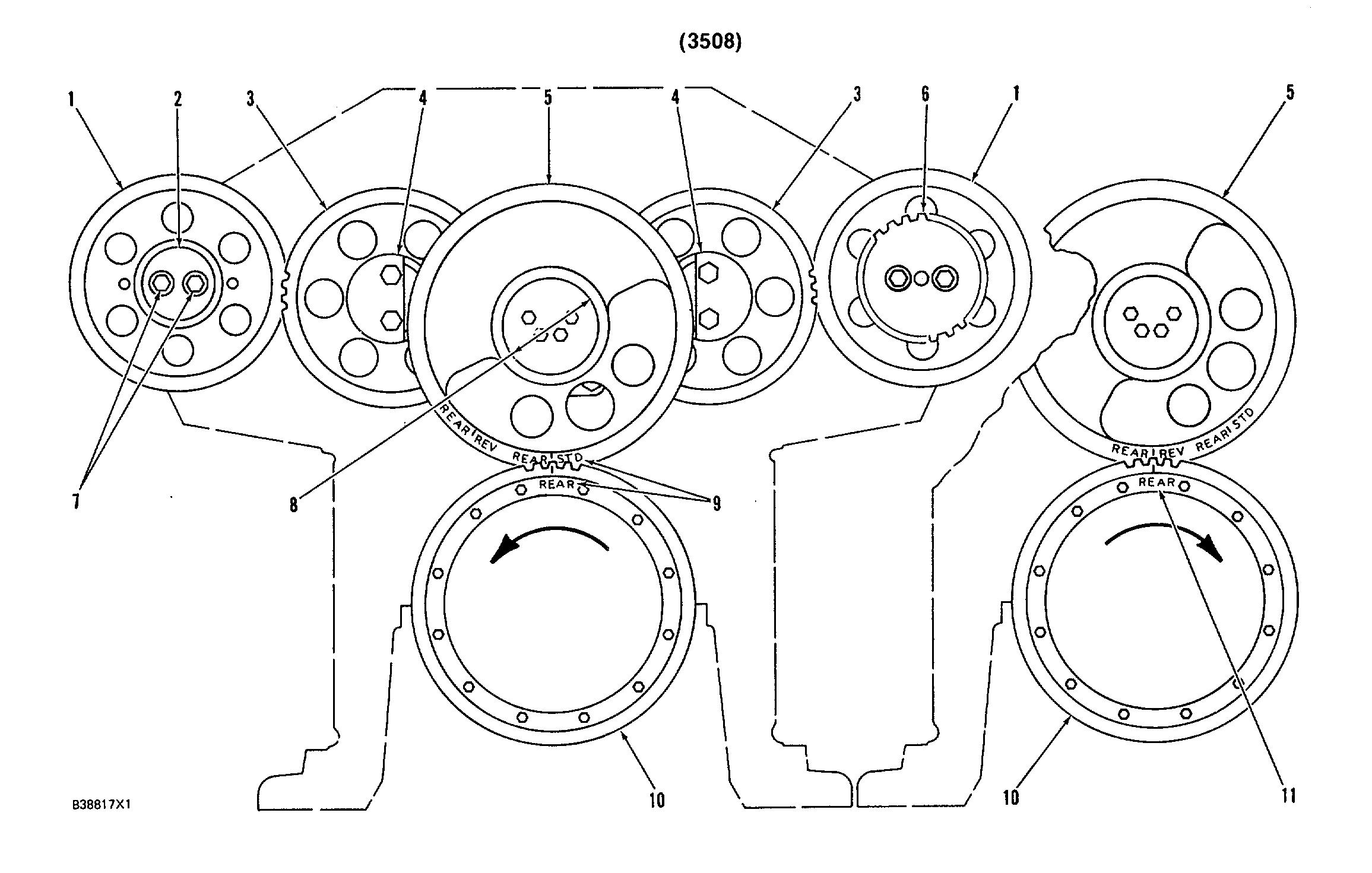
2REAR GEAR GROUP
(1) Camshaft drive gears. (2) Plate. (3) Camshaft idler gears (4) Diameter of shafts (new) 74.900 + 0 015 mm (2.9488 + .0006 in.) Bore in bearings (after assembly) ..................................75.000+0.055 mm (2.9528 + .0022 in.) (5) Cluster idler gear (balancer gear). (6) Gear for hydramechanical protective system drive. (7) Bolts. tighten the bolts as follows: a. Put camshaft drive gears (1) in position on the camshafts. b. Use hand pressure to turn and hold camshaft drive gears (1) in their normal direction of rotation. This removes all gear clearance (backlash) between camshaft drive gears (1) and camshaft idler gears (3). c. Install plate (2) (on left side of engine) and/or drive gear (6) (on right side of engine) to hold camshaft drive gears (1) to each camshaft. d. Tighten bolts (7) in steps to a torque of 100 + 15 N-m (75 + 11 lb. ft.) e. Hit the face of plate (2) or drive gear (6), then tighten the bolts to a torque of 100 + 15 N-m (75 + 11 lb. ft.) f. Again hit the face of plate (2) or drive gear (6) and again tighten the bolts to a torque of ............................100 + 15 N-m (75 + 11 lb. ft.) NOTE: If necessary, repeat Step 7f until the bolts hold torque (can not be moved) to make sure the drive gears are in full contact with the taper on the camshafts.
(8) Diameter of shaft (new) 74.900 + 0 015 mm (2.9488 + .0006 in.) Bore in bearing (after assembly) ..................................75.000 + 0 053 mm (2.9528 + .0021 in.) Bearing joint must be in center of heavy section in gear at assembly. (9) Balancer gear marks must be in alignment with crankshaft gear marks as shown for SAE standard rotation engines (10) Crankshaft gear. (11) Balancer gear marks must be in alignment with crankshaft gear marks as shown for SAE opposite rotation engines
NOTE: FOR TORQUE VALUES NOT GIVEN, SEE THE FIRST45 PAGE OF SPECIFICATIONS FOR GENERAL TIGHTENING TORQUES 45
REAR GEAR GROUP
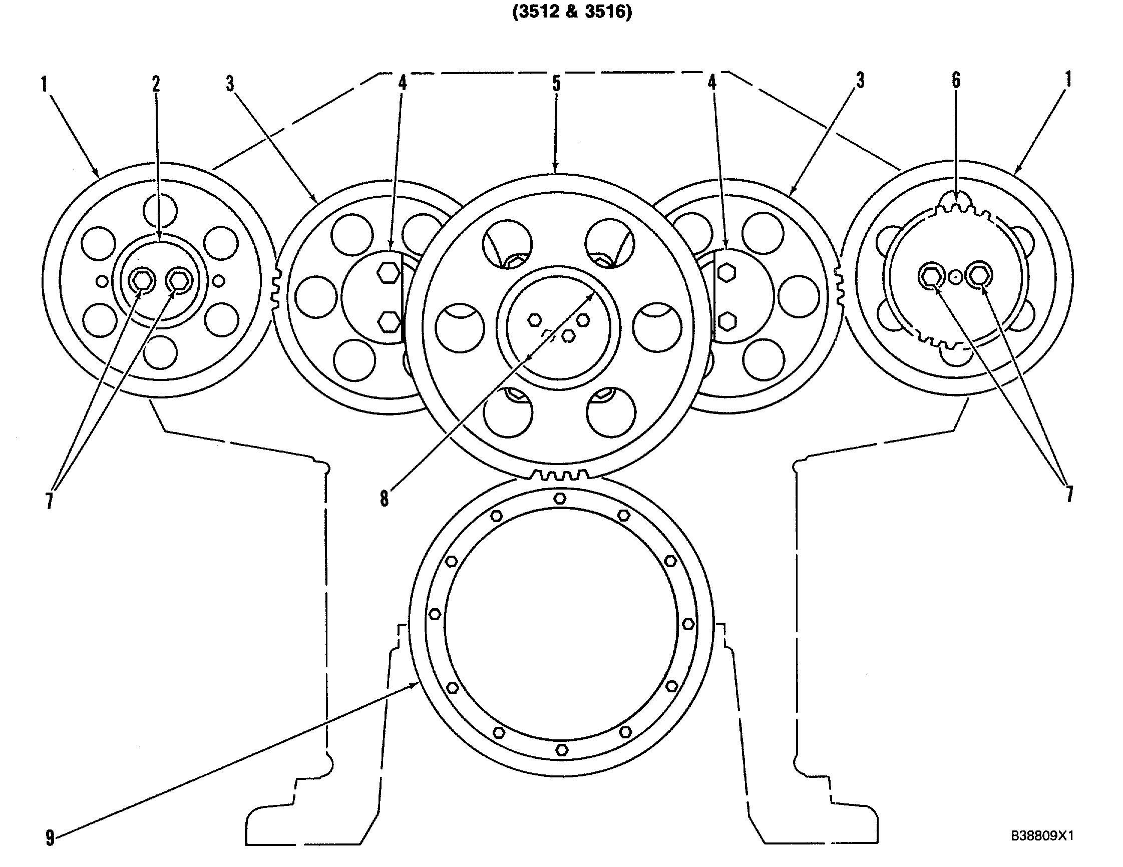
(1) Camshaft drive gears. (2) Plate. (3) Camshaft idler gears. (4) Diameter of shafts (new) 74.900 + 0.015 mm (2.9488 + .0006 in ) Bore in bearings (after assembly) ..................................75.000 0.055 mm (2.9528 + 0022 in.) (5) Cluster idler gear. (6) Gear for hydramechanical protective system drive. (7) Bolts. Tighten the bolts as follows: a. Put camshaft drive gears (1) in position on the camshafts. b. Use hand pressure to turn and hold camshaft drive gears (1) in their normal direction of rotation. This removes all gear clearance (backlash) between camshaft drive gears (1) and camshaft idler gears (3). c. Install plate (2) (on left side of engine) and/or drive gear (6) (on right side of engine) to hold camshaft drive gears (1) to each camshaft. d. Tighten bolts (7) in steps to a torque of of 100 ±15 N-m (75 + 11 lb. ft.) e. Hit the face of plate (2) or drive gear (6), then tighten the bolts to a torque of 100 f 15 N-m (75 ± 11 lb. ft.) f. Again hit the face of plate (2) or drive gear (6) and again tighten the bolts to a torque of ............................100 15 N-m (75 + 11 lb. ft.) NOTE: If necessary, repeat Step 7f until the bolts hold torque (can not be moved) to make sure the drive gears are in full contact with the taper on the camshafts.
(8) Diameter of shaft (new) 74.900 + 0.015 mm (2.9488 + 0006 in ) Bore in bearing (after assembly) ..................................75 000 + 0 053 mm (2 9528 t .0021 in ) (9) Crankshaft gear.


