6 minute read
Shutoff Control Group


3161 Standard and Generator Set Governors
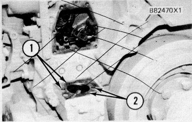
INSTALL SEALS 1. O-ring seals. 2. O-ring seals.
1. Make sure the four O-ring seals (1) and (2) are in position on the governor drive housing. Install the seal on the governor oil pump housing and put clean engine oil on all seals.

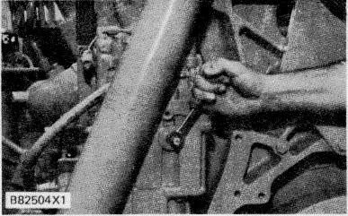
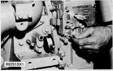
INSTALL GOVERNOR
2. Put the governor and cover gasket in position. Make sure the governor drive shaft and the spline drive are in correct alignment. Also, make sure the pin on the governor lever is engaged in the slot in the fuel control linkage stop lever.
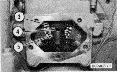
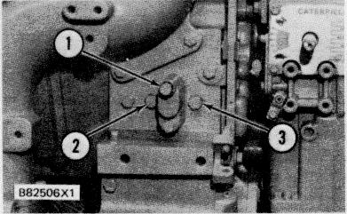
ALIGNMENT OF GOVERNOR AND DRIVE (Cover removed for photo illustration only)
NOTE: Be sure there is no binding, side load on the drive shaft, or looseness in the drive coupling. The maximum runout of the governor drive shaft and coupling must be less than 0.15 mm (.006 in.). Parts that do not fit correctly or are not in alignment can cause early wear, shaft seizure, or governor drive shaft failure.
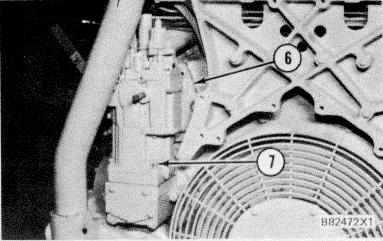
FASTEN GOVERNOR TO DRIVE HOUSING 6. Cover. 7. Bolts.
3. Move the governor to put cover (6) in correct alignment (square) with the front housing of the engine. With the governor in alignment, install and tighten bolts (7) to hold the governor to the drive housing.
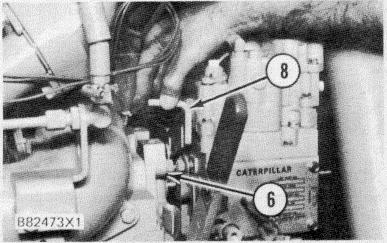
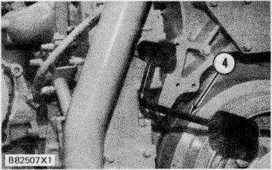
INSTALL COVER AND BRACKET 6. Cover. 8. Bracket.
4. Put cover (6) against the front drive housing and make sure the gasket is in alignment. Install and tighten the bolts. Check the governor terminal shaft for free movement, see Step 6.
5. Install bracket (8) as follows:
a. Install two bolts in the side of the governor.
b. Slide bracket (8) in place on the bolts.
Tighten the bolts enough to hold bracket (8) in position. The bracket must be free enough to move.
c. Install and tighten the two bolts that hold bracket (8) to the top of cover (6). This puts the bracket in correct alignment.
d. Tighten the two bolts that hold bracket (8) to the governor.
e. Check the governor terminal shaft for free movement, see Step 6.
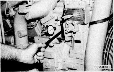
CHECK TERMINAL SHAFT MOVEMENT
6. Use a 7/16" wrench and move the governor terminal shaft several times in the ’FUEL ON" direction and release it. The terminal shaft must return completely to the "FUEL OFF" position each time. If the terminal shaft does not return, binding can be the result of parts not in correct alignment.
If the terminal shaft is binding, loosen the cover bolts, make an alignment of the cover again, then tighten the bolts again. Check for binding again with the above procedure. If this does not correct the binding, loosen the governor base to drive housing bolts. Move the governor and tighten the bolts again. Check for binding again with the above procedure.
NOTE: If the governor terminal shaft is binding after the above procedure, loosen the bolts for the fuel control linkage cover. Then loosen the bolts that hold the governor drive housing in position and move the housing to make an alignment of the cover bolt holes. Tighten all of the bolts again and check for terminal shaft binding.

CORRECT GOVERNOR OIL LEVEL
7. It is necessary to prime the governor. Remove the oil fill plug from the governor top cover. Add 1.8 liter (2 U.S. quarts) of clean engine oil to the governor before the first engine start up. Replace the plug in the top cover and tighten.
3161 Governor With Torque Rise
Tools Needed: 6V3139 Timing and Fuel Setting Tool Group. 5P4814 Collet. 6V3075 Dial Indicator (metric). 5P7263 Contact Point, 76.2 mm (3.00 in.) long.
FT1819g Governor Torque Arm Tool.
1. Put the governor in position on the engine as in Steps I through 3 for 3161 Standard and Generator Set Governors.
FUEL SETTING COVER 1. Synchronizing pin. 2. Plug. 3. Plug.
2. Remove plugs (2) and (3) from each side of the fuel setting cover.
3. Remove synchronizing pin (1) from the fuel setting cover and remove the washer from it. Install synchronizing pin (I) in the threaded hole for plug (2). Tighten the synchronizing pin (1) in position.
MOVE FUEL CONTROL LINKAGE AGAINST SYNCHRONIZING PIN 4. FT1819 Governor Torque Arm Tool.
4. Use FT1819 Governor Torque Arm Tool (4) to move and hold the governor terminal shaft in the "FUEL ON" direction. This puts the fuel control linkage stop lever against the end of synchronizing pin (1). The FT1819 Governor Torque Arm Tool is to be attached only with the engine shut down.
NOTE: A torque wrench and a 7/16 in. crowfoot wrench can be used to move the terminal shaft in the "FUEL ON" direction. Hold the governor terminal shaft and fuel control linkage against the synchronizing pin with 10 N-m (90 lb. in.) force to give an accurate dial indicator setting.
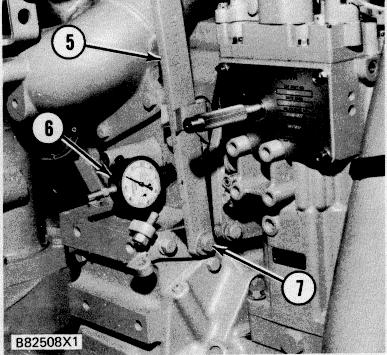
INSTALL DIAL INDICATOR 5. Manual fuel shutoff lever. 6. 6V3075 Dial Indicator with the 5P7263 Contact Point in the 5P4814 Collet. 7. Bolt.
5. Put 6V3075 Dial Indicator (6) with the 5P7263 Contact Point in the 5P4814 Collet. Install the dial indicator and collet in the threaded hole as shown. When the contact point seats against the fuel stop lever, slide the dial indicator in or out until the indicator reads zero. Now tighten the collet just enough to hold indicator at this position.
6. Remove tool (4) from the governor terminal shaft. Make sure the terminal shaft returns to the "FUEL OFF" position. 7. Remove bolt (7) and manual fuel shutoff lever (5).
8. Turn synchronizing pin (l) back out a minimum of 25 mm (I in.) or remove it completely.
ENGAGE GOVERNOR ZEROING PIN
9. The zeroing pin is engaged to hold the governor at a fixed position for setting the adjustable pin lever to synchronize the governor travel with the engine fuel control linkage travel. This pin is to be engaged only with the engine shut down.
Put a 5/32 inch hex wrench in the governor zeroing pin, push in and turn it counterclockwise until the roll pin locks squarely behind the bracket.
10. Install FT1819 Governor Torque Arm Tool (4) again to turn and hold the governor terminal shaft and linkage against the zeroing pin.
ADJ USTABLE PIN SETTING
11. With a 1/2 in. by 3/8 in. drive socket on a 12 in. extension and ratchet put the socket and extension between the cover and housing. Put the socket on the bolt that holds the adjustable pin lock and loosen the bolt.
NOTE: Later pins use a hex socket head bolt for use with 3/ 8in. drive sockets with a 12/4 in. hex bit.
Move the ratchet and extension up or down until the dial indicator reads zero Put 0.13 mm while the terminal shaft is held in the "FUEL ON" direction against the governor zeroing pin.


