3500 ENGINES
DISASSEMBLY AND ASSEMBLY HYDRAMECHANICAL SHUTOFF CONTROL
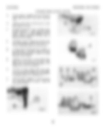
18.
Put the washer in position and use tool (C) to install snap ring (39) on the carrier assembly shaft.
19.
Install two bolts (40) to hold the gerotor pump group together as a unit.
20.
Put gerotor pump group (41) in position on the housing assembly. Make sure the speed sensing valve is correctly engaged with the carrier assembly and install the eight bolts to hold the pump in position.
21.
If necessary, make a replacement of dowels (45) and make sure they are 3.0 + 0.5 mm (.1 18 + .020 in.) above the surface of the valve body.
22.
Put spring (44) and pilot valve (43) in position in the valve body. Put clean engine oil on the 0ring seal and install plug (42) to hold the spring and pilot valve in position.
23.
Install three O-ring seals on air inlet shutoff valve (46) and put clean engine oil on the seals. Install valve (46) in the valve body and tighten it to a torque of 58 + 4 N•m (43 + 3 lb. ft.).
24.
Install three O-ring seals on rack shutoff valve (47) and put clean engine oil on the seals. Install valve (47) in the valve body and tighten it to a torque of 58 + 4 N•m (43 ± 3 lb. ft.).
25.
Install the seal in adapter (48) with tool group (A). Make sure the lip of the seal is toward the valve body as shown.
343


