3500 ENGINES
DISASSEMBLY AND ASSEMBLY HYDRAMECHANICAL SHUTOFF CONTROL
6.
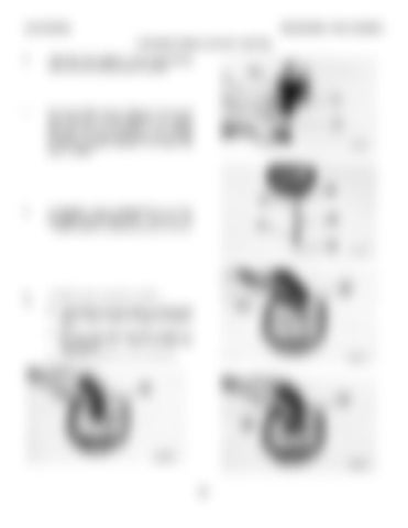
Install seat (16), spring (17) and speed sensing valve (9) on the housing assembly guide.
7.
Put clean engine oil on O-ring seal (18) and put 0-ring seal (18), plunger assembly (19), spring (20) and seat (21) in position in the housing assembly. Use tool (B) to install snap ring (22) to hold the plunger assembly, the spring and seat in position.
8.
If necessary, make a replacement of pin (24) and make sure pin (24) is 3.96 + 0.50 mm (.156 + .020 in.) above the bottom surface of the bore.
9. 10.
Install the gerotor assembly as follows: a) Install sleeve (23) and make sure the groove (slot) on sleeve (23) is in alignment with pin (24). b) Put the spring and brush (26) in position in the driven gear (25). Install driven gear (25) in the sleeve. c) Install drive gear (27) in the driven gear.
341


