3500 ENGINES
DISASSEMBLY AND ASSEMBLY TURBOCHARGERS (3508)
10.
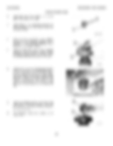
Install seal rings (10) on spacer ( 11 ) so the gaps in the rings are 180° apart.
11.
Install spacer ( 11) in backplate assembly (12) with the chamfer end of the spacer toward the cartridge housing.
12.
Make sure the oil passage in the cartridge housing and the backplate assembly are in alignment. Put the backplate assembly (12) in position on the cartridge housing.
13.
Install the locks and bolts to hold backplate assembly (12) to the cartridge housing. Tighten the bolts to a torque of 10 + 1.1 N•m (90 + 10 lb. in.) and bend the tabs of the locks on the bolts.
14.
Install tool (C) in tool (B). Put the turbine shaft in position in tooling (C). Put 6V2055 High Vacuum Grease in the groove for seal ring ( 14). Make sure the grease fills the groove approximately one half or more of the groove depth for the complete circumference of the groove to help make a carbon dam under the seal ring. Install seal ring (14) and shroud (15) on turbine shaft (13).
15.
Install the cartridge housing on the turbine shaft while spacer (11) is held in position. Make sure the seal ring on the turbine is fitted correctly in the cartridge housing.
16.
Put compressor wheel (16) in position on the turbine shaft.
319


