3161 GOVERNOR
TESTING AND ADJUSTING maximum runout of the governor drive shaft and coupling must be less than 0.15 mm (.006 in.). Parts that do not fit correctly or are not in alignment can cause early wear, shaft seizure, or governor drive shaft failure.
3161 Standard and Generator Set Governors
1.
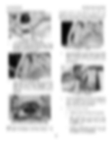
INSTALL SEALS 1. O-ring seals. 2. O-ring seals. Make sure the four O-ring seals (1) and (2) are in position on the governor drive housing. Install the seal on the governor oil pump housing and put clean engine oil on all seals.
FASTEN GOVERNOR TO DRIVE HOUSING 6. Cover. 7. Bolts. 3.
2.
Move the governor to put cover (6) in correct alignment (square) with the front housing of the engine. With the governor in alignment, install and tighten bolts (7) to hold the governor to the drive housing.
INSTALL GOVERNOR Put the governor and cover gasket in position. Make sure the governor drive shaft and the spline drive are in correct alignment. Also, make sure the pin on the governor lever is engaged in the slot in the fuel control linkage stop lever.
INSTALL COVER AND BRACKET 6. Cover. 8. Bracket. 4.
Put cover (6) against the front drive housing and make sure the gasket is in alignment. Install and tighten the bolts. Check the governor terminal shaft for free movement, see Step 6.
5.
Install bracket (8) as follows: a.
Install two bolts in the side of the governor.
b.
Slide bracket (8) in place on the bolts. Tighten the bolts enough to hold bracket (8) in position. The bracket must be free enough to move.
c.
Install and tighten the two bolts that hold bracket (8) to the top of cover (6). This puts the bracket in correct alignment.
ALIGNMENT OF GOVERNOR AND DRIVE (Cover removed for photo illustration only) NOTE: Be sure there is no binding, side load on the drive shaft, or looseness in the drive coupling. The
183


