Cat 3508 Diesel Engine Service Manual

Page 176

3161 GOVERNOR

SYSTEMS OPERATION

When the pilot valve plunger is lowered, oil under high pressure moves through the control port of the bushing, to the bottom side of the power piston, and the piston moves up. When the pilot valve plunger is raised, the oil from the bottom of the power piston is released to sump, and the higher oil pressure on top of the piston moves the piston down. When the engine is running at a steady state, the control land of the pilot valve plunger covers the ports in the ballhead bushing and the power piston does not move. The movement of the pilot valve plunger is controlled by the ballhead assembly.

The 3161 Standard and Torque Rise Governors are designed to operate with a 2 to 8 percent droop and have an internal droop pivot pin adjustment. The 3161 Generator Set Governor is designed to operate with a 0 to 4 percent droop. It has an external adjustment lever connected to the internal droop pivot pin. This permits droop adjustments to be on the outside of the governor housing.

Torque Rise Control

Ballhead Assembly The ballhead system has a ballhead, flyweights, speeder spring, thrust bearing, and speeder plug. The ballhead, as part of the pilot valve bushing, is turned by the drive coupling and drive shaft. As the ballhead turns, the centrifugal force causes the flyweights to pivot outward. At the same time, the force of the speeder spring pushes the thrust bearing down on the flyweight toes against the centrifugal force of the flyweights. When the speeder plug is pushed down this increases the downward pressure on the speeder spring, and the governor speed setting is increased. The engine then runs at a higher speed and puts a higher centrifugal force on the flyweights to equal the speeder spring force and put the system back in balance.

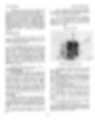
TORQUE RISE COMPONENTS 1. Torque control lever. 2. Cam.

Speeder spring force or speed setting is controlled through the speed setting shaft. Compensation System The compensation system has a needle valve and a buffer piston with two springs. This system can be adjusted to give the desired rate of governor control and engine speed stability. Since the governor makes an adjustment rapidly to a change in engine load or speed setting, the engine can go into a "hunt" condition (temporary increase and decrease in engine speed) if too much adjustment is made. The purpose of the compensation system is to prevent overcorrection to the engine load or speed setting change. The system uses a pressure differential that is applied across the compensation land of the pilot valve plunger to give a stable governor control. Speed Droop The 3161 Governor is an isochronous governor with the ability to operate with droop by the adjustment of an internal droop pivot pin. The governor may be used with droop to allow for load division between two or more engines connected to a single shaft, or for operating in parallel. The speed droop of a governor is the percent that the engine speed drops between high idle and full load.

The torque rise control consists of a cam that makes the governor give more fuel to the engine under lug conditions. Different percentages of torque rise can be selected by changing the cam to a programmed rate of rise. This change can be made on or off the engine. Cam selection and high idle settings must be based on factory recommendations. The torque rise control is factory installed. It is not practical to install it in the field. The torque rise cam has three distinct profiles: the base circle area (3); the approach ramp area (4); and the cam lift area (5). The "base circle area" is a radius that does not lift the cam follower. The cam follower must be positioned on the base circle area when the dial indicator is zeroed, for a check or adjustment of the torque rise setting. The "approach ramp area" is the "transition area" from the base circle to the cam lift area. The "cam lift area" is the area on the cam that lifts the cam follower and torque rise pilot valve lever, which allows additional fuel for torque rise greater than the natural torque rise of the engine.

160


Turn static files into dynamic content formats.

Create a flipbook

Articles inside

Pistons

3min
pages 396-397

Spacer Plates

2min
pages 391-392

Front Balancer Group

1min
pages 385-386

Crankshaft Main Bearings

4min
pages 393-395

Rear Gear Group

3min
pages 387-390

Connecting Rod Bearings

1min
page 384

Bridge Dowels

2min
pages 382-383

Cylinder Heads

4min
pages 377-380

Fuel Injectors

3min
pages 369-370

Valves

1min
page 381

Valve Covers

1min
page 365

Rocker Shafts and Push Rods

4min
pages 366-368

Fuel Injection Control Linkage

6min
pages 371-376

Flywheel Housing

1min
pages 363-364

Flywheel

1min
page 362

Crankshaft Front Seal and Wear Sleeve

2min
pages 354-355

Crankshaft Rear Seal and Wear Sleeve

2min
pages 356-357

Front Drive Housing

4min
pages 358-361

Oil and Water Pump Drive

1min
pages 350-352

Crankshaft Vibration Damper

1min
page 353

Accessory Drive (Front

1min
pages 347-349

Hydramechanical Shutoff Drive

1min
pages 345-346

Hydramechanical Shutoff Control

12min
pages 332-344

Governor Drive

3min
pages 328-331

Governor

1min
pages 326-327

Exhaust Manifolds

1min
page 321

Aftercooler

2min
pages 322-325

Turbochargers

6min
pages 312-320

Oil Cooler

4min
pages 305-311

Oil Sequence Valves

1min
page 304

Oil Pan

2min
pages 300-303

Oil Filter Housing

5min
pages 293-299

Oil Pump

5min
pages 288-292

Fuel Priming Pump, Fuel Transfer Pump

4min
pages 283-287

Fuel Filter Housing

3min
pages 279-282

Water Pump

2min
pages 275-278

Water Temperature Regulators

1min
pages 272-274

Gauge Panel

6min
pages 259-261

Crankcase Breather

1min
pages 270-271

Wiring Diagrams

9min
pages 247-252

3500 Industrial Engines

6min
pages 253-256

Manual Shutoff

3min
pages 257-258

System Checks

1min
pages 243-244

Troubleshooting

4min
pages 239-242

Hydraulic Circuits, Later with an Alarm System

6min
pages 232-238

Hydraulic Circuits (Later

5min
pages 228-231

Electrical Switches

1min
page 210

Air Intake Shutoff

5min
pages 206-208

Shutoff Control Group

6min
pages 199-201

3500 Series Engines

4min
pages 197-198

Auxiliary Controls

2min
pages 192-196

Governor Preparation

3min
page 181

Governor Installation

8min
pages 182-186

Pneumatic Speed Setting Control Troubleshooting

3min
pages 178-179

Air Fuel Ratio Control Troubleshooting

7min
pages 176-177

Pneumatic Mid Speed Control

5min
pages 170-171

Air Fuel Ratio Control

4min
pages 167-168

Pneumatic Speed Control

3min
pages 165-166

Operation of the 3161 Governor

6min
pages 161-163

Governor Types

4min
pages 157-158

Caterpillar, 3161 Governor

2min
pages 155-156

Vibration Damper

1min
page 149

Starting System Air Starting System...................................Deleted

4min
pages 152-154

Checking Crankshaft Deflection (Bend

1min
page 148

Flywheel and Flywheel Housing

4min
pages 146-147

Water Temperature Regulator Test

2min
page 144

Pressure Cap Test

1min
page 142

Valve Clearance

3min
pages 137-138

Clearance Setting

2min
page 136

Air Fuel Ratio Control

1min
page 132

Bridge Adjustment Crankshaft Positions for Valve

2min
page 135

Fuel Setting Adjustment

2min
page 126

Engine Speed Measurement

2min
page 127

Fuel Setting

2min
page 125

Injector Synchronization

2min
pages 123-124

Startup Procedure

1min
page 120

Fuel Timing

1min
page 122

Camshaft Timing

2min
pages 118-119

Fuel Pressure

1min
page 116

Injector Test Sequence

9min
pages 110-115

Air Starting System

4min
pages 86-87

Leak Test for Injector Tester

1min
page 109

Contactor Switch (Water Temperature

4min
page 90

Camshafts

1min
page 85

Air Fuel Ratio Control

1min
pages 73-74

Woodward UG8 Lever Governors

2min
pages 71-72

Fuel Injector

2min
pages 68-70

Fuel Injection Control Linkage

1min
page 67

Engine Design

1min
pages 63-64

Fuel System

3min
pages 65-66

Systems Operation, 3500 Industrial Engines

1min
pages 61-62

Flywheel Housing Runout Alternators and Regulators.......................Deleted

11min
pages 53-60

Flywheel Housing Bore

1min
page 52

Rear Gear Group

2min
pages 45-46

Flywheel

1min
page 47

Upper Front Gear Group (7N4871

1min
page 44

Lower Front Gear Group

2min
pages 42-43

Front Balancer Group (3508

1min
page 41

Crankshaft Wear Sleeves and Seals

1min
page 40

Connecting Rod and Main Bearing Journals

1min
page 38

Pistons and Rings

1min
page 36

Crankshaft

1min
page 39

Water Pump

1min
page 31

Cylinder Block

1min
page 34

Oil Cooler Bypass and Cooling Jet Sequence Valves

1min
page 30

Oil Filter Bypass Valve (Earlier

1min
page 28

Air Intake Shutoff

1min
pages 23-25

and Taperlock Studs

5min
pages 3-4

Fuel Injection Control Group

3min
page 10

Oil Pump

1min
pages 26-27

Camshafts

3min
pages 12-13

Oil Filter Bypass Valve (Later

1min
page 29

Engine Design

5min
pages 5-7
Issuu converts static files into: digital portfolios, online yearbooks, online catalogs, digital photo albums and more. Sign up and create your flipbook.
Cat 3508 Diesel Engine Service Manual by www.heydownloads.com - Issuu