Cat 3508 Diesel Engine Service Manual

Page 152

AIR INLET AND EXHAUST SYSTEM

TESTING AND ADJUSTING

EXHAUST TEMPERATURE

Valves Valve removal and installation is easier with use of the IP3527 Valve Spring Compressor Assembly. Valve Seat Inserts To remove and install valve seat inserts, use the 6V4805 Valve Seat Extractor Group. For installation, lower the temperature of the insert before it is installed in the head. Valve Guides Tools needed to remove and install valve guides are the 5P1729 Bushing and 7M3975 Driver. The counterbore in the driver bushing installs the guide to the correct height. Use a I P7451 Valve Guide Honing Group to make a finished bore in the valve guide after installation of the guide in the head. Special Instruction, Form No. SMHS7526 gives an explanation for this procedure. Grind the valves after the new valve guides are installed.

1P3060 PYROMETER GROUP Use the IP3060 Pyrometer Group to check exhaust temperature. Special Instruction, Form No. SMHS7179 is with the tool group and gives instructions for the test procedure.

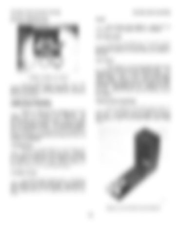
Checking Valve Guide Bores

CRANKCASE (CRANKSHAFT COMPARTMENT) PRESSURE

Use the 5P3536 Valve Guide Gauge Group to check the bore of the valve guides. Special Instruction, Form No. GMG02562 gives complete and detailed instructions for use of the 5P3536 Valve Guide Gauge Group.

Pistons or rings that have damage can be the cause of too much pressure in the crankcase. This condition will cause the engine to run rough. There will also be more than the normal amount of fumes coming from the crankcase breather. This crankcase pressure can also cause the element for the crankcase breather to have a restriction in a very short time. It can also be the cause of oil leakage at gaskets and seals that would not normally have leakage. COMPRESSION An engine that runs rough can have a leak at the valves, or have valves that need adjustment. Removal of the head and inspection of the valves and valve seats is necessary to find those small defects that do not normally cause a problem. Repair of these problems is normally done when reconditioning the engine. CYLINDER HEADS The cylinder heads have valve seat inserts, valve guides and bridge dowels that can be removed when they are worn or have damage. Replacement of these components can be made with the tools that follow.

SP3536 VALVE GUIDE GAUGE GROUP 134


Turn static files into dynamic content formats.

Create a flipbook

Articles inside

Pistons

3min
pages 396-397

Spacer Plates

2min
pages 391-392

Front Balancer Group

1min
pages 385-386

Crankshaft Main Bearings

4min
pages 393-395

Rear Gear Group

3min
pages 387-390

Connecting Rod Bearings

1min
page 384

Bridge Dowels

2min
pages 382-383

Cylinder Heads

4min
pages 377-380

Fuel Injectors

3min
pages 369-370

Valves

1min
page 381

Valve Covers

1min
page 365

Rocker Shafts and Push Rods

4min
pages 366-368

Fuel Injection Control Linkage

6min
pages 371-376

Flywheel Housing

1min
pages 363-364

Flywheel

1min
page 362

Crankshaft Front Seal and Wear Sleeve

2min
pages 354-355

Crankshaft Rear Seal and Wear Sleeve

2min
pages 356-357

Front Drive Housing

4min
pages 358-361

Oil and Water Pump Drive

1min
pages 350-352

Crankshaft Vibration Damper

1min
page 353

Accessory Drive (Front

1min
pages 347-349

Hydramechanical Shutoff Drive

1min
pages 345-346

Hydramechanical Shutoff Control

12min
pages 332-344

Governor Drive

3min
pages 328-331

Governor

1min
pages 326-327

Exhaust Manifolds

1min
page 321

Aftercooler

2min
pages 322-325

Turbochargers

6min
pages 312-320

Oil Cooler

4min
pages 305-311

Oil Sequence Valves

1min
page 304

Oil Pan

2min
pages 300-303

Oil Filter Housing

5min
pages 293-299

Oil Pump

5min
pages 288-292

Fuel Priming Pump, Fuel Transfer Pump

4min
pages 283-287

Fuel Filter Housing

3min
pages 279-282

Water Pump

2min
pages 275-278

Water Temperature Regulators

1min
pages 272-274

Gauge Panel

6min
pages 259-261

Crankcase Breather

1min
pages 270-271

Wiring Diagrams

9min
pages 247-252

3500 Industrial Engines

6min
pages 253-256

Manual Shutoff

3min
pages 257-258

System Checks

1min
pages 243-244

Troubleshooting

4min
pages 239-242

Hydraulic Circuits, Later with an Alarm System

6min
pages 232-238

Hydraulic Circuits (Later

5min
pages 228-231

Electrical Switches

1min
page 210

Air Intake Shutoff

5min
pages 206-208

Shutoff Control Group

6min
pages 199-201

3500 Series Engines

4min
pages 197-198

Auxiliary Controls

2min
pages 192-196

Governor Preparation

3min
page 181

Governor Installation

8min
pages 182-186

Pneumatic Speed Setting Control Troubleshooting

3min
pages 178-179

Air Fuel Ratio Control Troubleshooting

7min
pages 176-177

Pneumatic Mid Speed Control

5min
pages 170-171

Air Fuel Ratio Control

4min
pages 167-168

Pneumatic Speed Control

3min
pages 165-166

Operation of the 3161 Governor

6min
pages 161-163

Governor Types

4min
pages 157-158

Caterpillar, 3161 Governor

2min
pages 155-156

Vibration Damper

1min
page 149

Starting System Air Starting System...................................Deleted

4min
pages 152-154

Checking Crankshaft Deflection (Bend

1min
page 148

Flywheel and Flywheel Housing

4min
pages 146-147

Water Temperature Regulator Test

2min
page 144

Pressure Cap Test

1min
page 142

Valve Clearance

3min
pages 137-138

Clearance Setting

2min
page 136

Air Fuel Ratio Control

1min
page 132

Bridge Adjustment Crankshaft Positions for Valve

2min
page 135

Fuel Setting Adjustment

2min
page 126

Engine Speed Measurement

2min
page 127

Fuel Setting

2min
page 125

Injector Synchronization

2min
pages 123-124

Startup Procedure

1min
page 120

Fuel Timing

1min
page 122

Camshaft Timing

2min
pages 118-119

Fuel Pressure

1min
page 116

Injector Test Sequence

9min
pages 110-115

Air Starting System

4min
pages 86-87

Leak Test for Injector Tester

1min
page 109

Contactor Switch (Water Temperature

4min
page 90

Camshafts

1min
page 85

Air Fuel Ratio Control

1min
pages 73-74

Woodward UG8 Lever Governors

2min
pages 71-72

Fuel Injector

2min
pages 68-70

Fuel Injection Control Linkage

1min
page 67

Engine Design

1min
pages 63-64

Fuel System

3min
pages 65-66

Systems Operation, 3500 Industrial Engines

1min
pages 61-62

Flywheel Housing Runout Alternators and Regulators.......................Deleted

11min
pages 53-60

Flywheel Housing Bore

1min
page 52

Rear Gear Group

2min
pages 45-46

Flywheel

1min
page 47

Upper Front Gear Group (7N4871

1min
page 44

Lower Front Gear Group

2min
pages 42-43

Front Balancer Group (3508

1min
page 41

Crankshaft Wear Sleeves and Seals

1min
page 40

Connecting Rod and Main Bearing Journals

1min
page 38

Pistons and Rings

1min
page 36

Crankshaft

1min
page 39

Water Pump

1min
page 31

Cylinder Block

1min
page 34

Oil Cooler Bypass and Cooling Jet Sequence Valves

1min
page 30

Oil Filter Bypass Valve (Earlier

1min
page 28

Air Intake Shutoff

1min
pages 23-25

and Taperlock Studs

5min
pages 3-4

Fuel Injection Control Group

3min
page 10

Oil Pump

1min
pages 26-27

Camshafts

3min
pages 12-13

Oil Filter Bypass Valve (Later

1min
page 29

Engine Design

5min
pages 5-7
Issuu converts static files into: digital portfolios, online yearbooks, online catalogs, digital photo albums and more. Sign up and create your flipbook.
Cat 3508 Diesel Engine Service Manual by www.heydownloads.com - Issuu