Cat 3508 Diesel Engine Service Manual

Page 132

FUEL SYSTEM

TESTING AND ADJUSTING Look at test pressure gauge (2) during the procedure in Step 3. High pressure can come rapidly, so be careful. PRESSURE MUST NOT GO ABOVE 14 000 kPa. 3.

Pump the tester just fast enough to maintain a pressure between 10 000 and 14 000 kPa on gauge (2). With this amount of pressure on the injector, make a thorough visual inspection of the injector for any leakage.

4.

There must be no leakage at the seals. If there is leakage, new seals must be installed. Make this repair before any other tests are started.

LOAD CELL PRESSURE RANGE 5.

The Load Cell Pressure for a new or used injector must be 3100 to 4100 kPa. If pressure is not within this pressure range, do not use the injector again.

IV. External Leakage

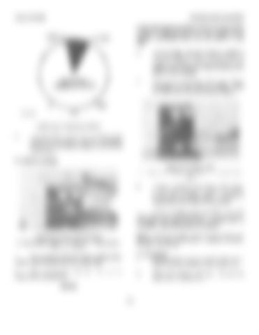
INJECTOR UNDER TEST 2. Test pressure gauge. 4. Handle. 9. Test pressure valve. 5.

If there is leakage at any part of the injector (except at the rack hole or from the injector tip), do not use the injector again. A repair or replacement of the injector must be made.

If there is leakage at the rack hole or from the injector tip, do the LEAKDOWN RATE TEST and the TIP LEAKAGE TEST (after EXTERNAL LEAKAGE TEST is complete) to see if the leakage is excessive. NOTE: If there is to be a repair to the injector, see REPAIR OF UNIT INJECTORS in Special Instruction, Form No. SEHS8190.

INJECTOR INSTALLED FOR TEST 2. Test pressure gauge. 4. Handle. 9. Test pressure valve. 25. Injector. 1. Remove all fluid from the injector holding block, injector body and injector tip with a clean cloth.

V. Tip Leakage 1. Remove all fluid from the injector holding block, injector body and injector tip with a clean cloth.

2. Close test pressure valve (9). injector tip is completely dry.

2.

Be sure the

NOTICE

114

Close test pressure valve (9). injector tip is completely dry.

Be sure the


Turn static files into dynamic content formats.

Create a flipbook

Articles inside

Pistons

3min
pages 396-397

Spacer Plates

2min
pages 391-392

Front Balancer Group

1min
pages 385-386

Crankshaft Main Bearings

4min
pages 393-395

Rear Gear Group

3min
pages 387-390

Connecting Rod Bearings

1min
page 384

Bridge Dowels

2min
pages 382-383

Cylinder Heads

4min
pages 377-380

Fuel Injectors

3min
pages 369-370

Valves

1min
page 381

Valve Covers

1min
page 365

Rocker Shafts and Push Rods

4min
pages 366-368

Fuel Injection Control Linkage

6min
pages 371-376

Flywheel Housing

1min
pages 363-364

Flywheel

1min
page 362

Crankshaft Front Seal and Wear Sleeve

2min
pages 354-355

Crankshaft Rear Seal and Wear Sleeve

2min
pages 356-357

Front Drive Housing

4min
pages 358-361

Oil and Water Pump Drive

1min
pages 350-352

Crankshaft Vibration Damper

1min
page 353

Accessory Drive (Front

1min
pages 347-349

Hydramechanical Shutoff Drive

1min
pages 345-346

Hydramechanical Shutoff Control

12min
pages 332-344

Governor Drive

3min
pages 328-331

Governor

1min
pages 326-327

Exhaust Manifolds

1min
page 321

Aftercooler

2min
pages 322-325

Turbochargers

6min
pages 312-320

Oil Cooler

4min
pages 305-311

Oil Sequence Valves

1min
page 304

Oil Pan

2min
pages 300-303

Oil Filter Housing

5min
pages 293-299

Oil Pump

5min
pages 288-292

Fuel Priming Pump, Fuel Transfer Pump

4min
pages 283-287

Fuel Filter Housing

3min
pages 279-282

Water Pump

2min
pages 275-278

Water Temperature Regulators

1min
pages 272-274

Gauge Panel

6min
pages 259-261

Crankcase Breather

1min
pages 270-271

Wiring Diagrams

9min
pages 247-252

3500 Industrial Engines

6min
pages 253-256

Manual Shutoff

3min
pages 257-258

System Checks

1min
pages 243-244

Troubleshooting

4min
pages 239-242

Hydraulic Circuits, Later with an Alarm System

6min
pages 232-238

Hydraulic Circuits (Later

5min
pages 228-231

Electrical Switches

1min
page 210

Air Intake Shutoff

5min
pages 206-208

Shutoff Control Group

6min
pages 199-201

3500 Series Engines

4min
pages 197-198

Auxiliary Controls

2min
pages 192-196

Governor Preparation

3min
page 181

Governor Installation

8min
pages 182-186

Pneumatic Speed Setting Control Troubleshooting

3min
pages 178-179

Air Fuel Ratio Control Troubleshooting

7min
pages 176-177

Pneumatic Mid Speed Control

5min
pages 170-171

Air Fuel Ratio Control

4min
pages 167-168

Pneumatic Speed Control

3min
pages 165-166

Operation of the 3161 Governor

6min
pages 161-163

Governor Types

4min
pages 157-158

Caterpillar, 3161 Governor

2min
pages 155-156

Vibration Damper

1min
page 149

Starting System Air Starting System...................................Deleted

4min
pages 152-154

Checking Crankshaft Deflection (Bend

1min
page 148

Flywheel and Flywheel Housing

4min
pages 146-147

Water Temperature Regulator Test

2min
page 144

Pressure Cap Test

1min
page 142

Valve Clearance

3min
pages 137-138

Clearance Setting

2min
page 136

Air Fuel Ratio Control

1min
page 132

Bridge Adjustment Crankshaft Positions for Valve

2min
page 135

Fuel Setting Adjustment

2min
page 126

Engine Speed Measurement

2min
page 127

Fuel Setting

2min
page 125

Injector Synchronization

2min
pages 123-124

Startup Procedure

1min
page 120

Fuel Timing

1min
page 122

Camshaft Timing

2min
pages 118-119

Fuel Pressure

1min
page 116

Injector Test Sequence

9min
pages 110-115

Air Starting System

4min
pages 86-87

Leak Test for Injector Tester

1min
page 109

Contactor Switch (Water Temperature

4min
page 90

Camshafts

1min
page 85

Air Fuel Ratio Control

1min
pages 73-74

Woodward UG8 Lever Governors

2min
pages 71-72

Fuel Injector

2min
pages 68-70

Fuel Injection Control Linkage

1min
page 67

Engine Design

1min
pages 63-64

Fuel System

3min
pages 65-66

Systems Operation, 3500 Industrial Engines

1min
pages 61-62

Flywheel Housing Runout Alternators and Regulators.......................Deleted

11min
pages 53-60

Flywheel Housing Bore

1min
page 52

Rear Gear Group

2min
pages 45-46

Flywheel

1min
page 47

Upper Front Gear Group (7N4871

1min
page 44

Lower Front Gear Group

2min
pages 42-43

Front Balancer Group (3508

1min
page 41

Crankshaft Wear Sleeves and Seals

1min
page 40

Connecting Rod and Main Bearing Journals

1min
page 38

Pistons and Rings

1min
page 36

Crankshaft

1min
page 39

Water Pump

1min
page 31

Cylinder Block

1min
page 34

Oil Cooler Bypass and Cooling Jet Sequence Valves

1min
page 30

Oil Filter Bypass Valve (Earlier

1min
page 28

Air Intake Shutoff

1min
pages 23-25

and Taperlock Studs

5min
pages 3-4

Fuel Injection Control Group

3min
page 10

Oil Pump

1min
pages 26-27

Camshafts

3min
pages 12-13

Oil Filter Bypass Valve (Later

1min
page 29

Engine Design

5min
pages 5-7
Issuu converts static files into: digital portfolios, online yearbooks, online catalogs, digital photo albums and more. Sign up and create your flipbook.