Mustang Compact Excavator ME12002 Service Manual_909768 - PDF DOWNLOAD

Page 222

JOHN DEERE ENGINE 4045TF270 (SN AC02633 AND UP)

ME12002

Servicing the Fuel Injection Pump

is running or still warm, damage to the rotating pump components can occur.

Removing the Fuel Injection Pump

2. If installed, remove the cutoff cable and throttle control linkage.

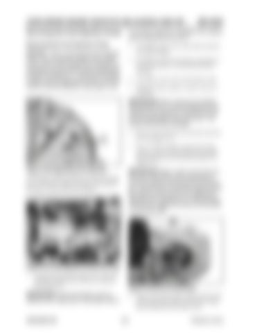
NOTICE: Prior to removing the fuel injection pump, use the flywheel rotation tool to (both rocker arms on this cylinder are movable) turn the engine to the top dead center compression position of cylinder no. 1, and keep the engine in place with the adjustment pin (A), as for setting the valve tip clearance. See Figure 4-30.

3. If installed, remove the electric connection to the stop solenoid or to the throttle position solenoid. 4. If installed, remove the cold-starting switch. 5. Mark the electric cables to ensure correct reassembly.

IMPORTANT:When loosening and tightening fuel feed lines on the fuel injection pump, ALWAYS use a spanner to hold the lock nut and avoid damage to the pump ports. This avoids internal pump damage. A

6. Remove fuel return line (A) and fuel feed line (C). See Figure 4-31. 7. Use a 17 mm crowfoot wrench with a long socket to remove all fuel feed lines (pressure lines) (B) from the fuel injection pump. See Figure 4-31.

Figure 4-30 Adjustment Pin Opening

IMPORTANT:Make a mark on the drive pin-

All Stanadyne DB2 and DB4 fuel injection pumps have a fixed drive shaft (it remains in the pump if the latter is removed from the engine).

ion and on the pinion of the wheel gear to mark the position of the pinions for re-assembly. The drive pinion of the fuel injection pump fits exactly on the conical drive shaft and is adjusted with a female pin or a Woodruff key. This secures it against turning it out of position on the pump shaft.

A

B

E

D

C

Figure 4-31 Fuel Injection Pump Fuel Lines 1. Clean the fuel injection pump, lines, and area around the pump with a solvent or steam jet. See Figure 4-31.

IMPORTANT:If the fuel injection pump is cleaned with a steam jet or cold water while it

909768/BP1207

Figure 4-32 End of Pump Shaft 8. Remove the lock nut and washer from the end of the pump shaft. Make sure that the washer does not drop into the control cover. 214

Printed in U.S.A


Turn static files into dynamic content formats.

Create a flipbook

Articles inside

ME12002TROUBLESHOOTING

1min
page 311

ME12002TROUBLESHOOTING

1min
pages 309-310

JOHNDEEREENGINE4045TF270(SNAC02633ANDUP)ME12002

43min
pages 230-235, 237-298

JOHNDEEREENGINE4045TF270(SNAC02633ANDUP)ME12002

3min
pages 226-229

JOHNDEEREENGINE4045TF270(SNAC02633ANDUP)ME12002

5min
pages 222-225

JOHNDEEREENGINE4045TF270(SNAC02633ANDUP)ME12002

4min
pages 216-221

HYDRAULICSYSTEMME12002

2min
pages 208, 211-215

ME12002HYDRAULICSYSTEM

1min
pages 205-207

ME12002HYDRAULICSYSTEM

1min
pages 203-204

HYDRAULICSYSTEMME12002

1min
page 202

ME12002HYDRAULICSYSTEM

1min
page 201

ME12002HYDRAULICSYSTEM

1min
pages 199-200

HYDRAULICSYSTEMME12002

1min
pages 188-190

ME12002HYDRAULICSYSTEM

1min
page 187

HYDRAULICSYSTEMME12002

1min
page 186

ME12002HYDRAULICSYSTEM

1min
page 185

ME12002HYDRAULICSYSTEM

3min
pages 179-184

HYDRAULICSYSTEMME12002

1min
page 174

HYDRAULICSYSTEMME12002

2min
pages 168-173

ME12002HYDRAULICSYSTEM

3min
pages 161-167

HYDRAULICSYSTEMME12002

1min
page 160

ME12002HYDRAULICSYSTEM

1min
page 159

ME12002HYDRAULICSYSTEM

1min
pages 155-156

ME12002HYDRAULICSYSTEM

1min
pages 153-154

HYDRAULICSYSTEMME12002

1min
page 152

ME12002HYDRAULICSYSTEM StraightTravelSpool(noadditionalactuation)

1min
page 151

ME12002HYDRAULICSYSTEM

1min
pages 149-150

HYDRAULICSYSTEMME12002

3min
pages 140-146

ME12002HYDRAULICSYSTEM

1min
page 139

ME12002HYDRAULICSYSTEM

1min
pages 137-138

RegenerationCircuit

3min
pages 132-136

HYDRAULICSYSTEMME12002

3min
pages 128-131

ME12002HYDRAULICSYSTEM

1min
page 125

OperatingMainRelief

1min
page 124

HYDRAULICSYSTEMME12002

1min
page 124

ME12002HYDRAULICSYSTEM OperatingPilotPressure

1min
page 123

FineMetering

1min
page 117

HYDRAULICSYSTEMME12002 ValveStructure

1min
page 116

HYDRAULICSYSTEMME12002

1min
pages 104-109

HYDRAULICSYSTEMME12002

1min
pages 102-103

ME12002HYDRAULICSYSTEM

1min
page 101

HYDRAULICSYSTEMME12002

1min
page 100

ME12002HYDRAULICSYSTEM

1min
page 99

ME12002HYDRAULICSYSTEM

1min
page 97

ME12002HYDRAULICSYSTEM

1min
page 95

HYDRAULICSYSTEMME12002

1min
page 94

HYDRAULICSYSTEMME12002

1min
page 92

HYDRAULICSYSTEMME12002

5min
pages 82-91

HYDRAULICSYSTEMME12002

2min
pages 78-81

ME12002HYDRAULICSYSTEM

1min
page 77

HYDRAULICSYSTEMME12002

1min
page 76

HYDRAULICSYSTEMME12002

1min
page 74

HYDRAULICSYSTEMME12002

1min
pages 72-73

MAINTENANCEME12002

4min
pages 54-57, 59-64

MAINTENANCEME12002

1min
pages 52-53

MAINTENANCEME12002

2min
pages 48-51

MAINTENANCEME12002 HydraulicPumpPartInspection

2min
pages 42-47

ME12002TECHNICALDATA

1min
pages 13-14
Issuu converts static files into: digital portfolios, online yearbooks, online catalogs, digital photo albums and more. Sign up and create your flipbook.
Mustang Compact Excavator ME12002 Service Manual_909768 - PDF DOWNLOAD by www.heydownloads.com - Issuu