1 minute read
HYDRAULICSYSTEMME12002


27.Apply adhesive (Loctite #241 or equivalent) to the surfaces of hexagon socket screws (472) as shown. See Figure 3-258.
30.Install the top of bellows (501) into block (420). See Figure 3-261.
28.Tighten hexagon socket screw (472) to the specified torque. See Figure 3-259.
31.Apply anticorrosion oil (WD-40 or equivalent) inside of bellows (501). See Figure 3-262.
32.Install the bottom of bellows (501) into the groove in cover (201). See Figure 3-261.
IMPORTANT:If the bellows are not tightly installed into the groove (and are loose), bellows resistance to dust and water decreases.
29.Tilt block (420), apply grease to the top of push rod (214) and inject grease into grease cap (203) of plug (202) as shown. See Figure 3-260.
IMPORTANT:Apply and inject grease using a spatula made of soft material. Do not damage the push rod and plug surfaces.
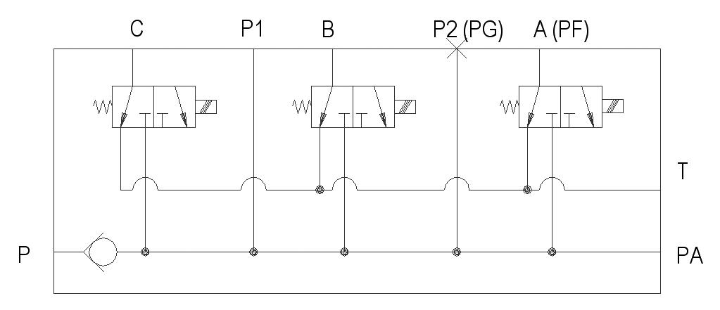
HydraulicSystemComponents
TTank line
PPump supply hose <- gear pump
P1 Port drive counter balancing -> main valve block
P2Swing unit - park brake
A 2nd drive speed - drive unit
BMicroswitch/safety valve/joysticks
COil flow limitation switch P1 u. P2
HydraulicDiagram