3 minute read
JOHNDEEREENGINE4045TF270(SNAC02633ANDUP)ME12002


4.Pull out the injection nozzle using the injection nozzle extractor kit (C), or by using the adapter and the slide grip. See Figure 4-40 on page217.
5.Clean the injection nozzle hole using the injection nozzle cleaning tool.
6.Remove dirt from the hole with compressed air and cover the hole to keep out foreign materials.
7.Place the nozzle in solvent or clean diesel fuel until the nozzle is clean. Be sure that the carbon stop seal groove is fully immersed.
IMPORTANT:Do not scratch or damage the coating on the nozzle housing above the carbon seal groove.
8.Clean the nozzle tip with a brass wire brush after it has been immersed.
TestingtheFuelInjectionNozzles
2.Position the nozzle tip below the top of beaker (D) and 30° from the bottom of beaker (D) to contain all spray in beaker (D), as nozzle spray pattern projects at an angle toward the nozzle center line. See Figure 4-41.
NOTICE: Rapidly operating the pump handle causes inaccurate cracking pressure readings and undue wear on the gauge.
3.Pump the handle several times to force air from the lines and determine the correct pump speed for fuel atomization (atomization is the conversion of bulk liquid into a spray or mist). See Figure 4-41.
4.Fully tighten all connections after forcing the air from the nozzle and line. See Figure 4-41.
CheckingtheOpeningPressure
1.Actuate the nozzle tester (A) rapidly several times to quickly seal the valve. See Figure 441.
2.Open the gauge valve, actuate the nozzle tester (A), and increase the pressure until the measuring instrument needle drops rapidly. This pressure measurement is the nozzle opening pressure for a new or used nozzle. See Figure 4-41.
NOTICE: If the nozzle opening pressure is not within the specified range, re-adjust the pressure and the valve stroke BEFORE checking clatter and injection pattern, otherwise these measurements may be affected.
Figure 4-41 Checking the Fuel Injection Nozzles
1.Connect Y900-3 and Y900-5 Adapters (C) and Y900-2 Fuel Line (B) (included with D01110AA Fuel Injection Nozzle Tester Adapter Set available from a John Deere dealer) to D01109AA OTC Portable Nozzle Tester (A), but do not fully tighten the connections. See Figure 4-41.
NOTICE: When using the JT25510 Bosch Bench Mounted Nozzle Tester, use the KJD10109 Fuel Line and connect line to tester and nozzle.
NOTICE: The actual nozzle opening pressure is not as important as an identical opening pressure for all nozzles. The opening pressure difference among the cylinders is a maximum 102 psi (7 bar).
CheckingtheClatter
1.Close the measuring instrument valve and actuate the nozzle tester at a speed that causes the nozzle to clatter. The nozzle should clatter softly and the injection pattern should be wide and finely atomized. Fuel injection nozzle tip (injection angle) 144°.
2.Write down the speed at which the nozzles began to clatter.
3.If the nozzle does not clatter, dismantle the nozzle and troubleshoot. The nozzle valve is possibly bent or cannot move in its guide because of residue.
NOTICE: The fuel ejects in a steady stream (not atomized) before the nozzle clatters. Actuate the nozzle tester (A) ten times while the pump operates at the correct speed for atomization. The nozzle must atomize during at least eight out of ten actuations (80%). See Figure 4-41.
CheckingforLeakage
1.Check the nozzle for fuel leakage at the valve seat by placing the nozzle tip, facing downward, onto nozzle tester (A). See Figure 4-41.
2.Actuate the pump handle rapidly.
3.Wipe the nozzle tip with a clean lint-free cloth.
4.Actuate the nozzle tester (A). Slowly increase and maintain the nozzle pressure to about 406508 psi (28-35 bar) below the specified opening pressure. See Figure 4-41. See “Checking the Opening Pressure” on page218.
5.Check for fuel leakage from the nozzle tip opening.
6.Wipe the nozzle with a clean lint-free cloth if fuel leaks within five seconds (slight dampness is permissible on used nozzles).
JOHNDEEREENGINE4045TF270(SNAC02633ANDUP)ME12002
DisassemblingtheFuelInjectionNozzles
1.Insert the nozzle into positioning clip (A) and secure positioning clip into a vice. See Figure 4-43.
2.Loosen the pressure setting lock nut (B). See Figure 4-43.
3.Remove lock nut (C) from the stroke set screw and raise the unit. See Figure 4-43.
4.Invert the nozzle. Remove and retain the pressure adjustment spring seat and the stroke adjustment.
NOTICE: Do not bend the stem during removal.
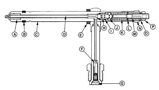
AssemblingtheFuelInjectionNozzles
Nozzle housingSpring seatPressure set screw lock nut
SpacerPressure adjustment springStroke set screw
Positioning clipWasherPressure set screw
Nozzle valveStroke set screw lock nutFastening clips
1.Install spacer (B) onto nozzle housing (A). See Figure 4-44.
2.Install positioning clip (C) onto nozzle housing (A) so that the flanges face down.
3.Install the three remaining fastening clips (L) onto nozzle housing (A).
4.Dip nozzle valve (D) into clean fuel.
5.Insert nozzle valve (D) into nozzle housing (A).
6.Screw stroke set screw (J) into pressure set screw (K) until the tip barely penetrates into the screw.
7.Invert the set screw unit.
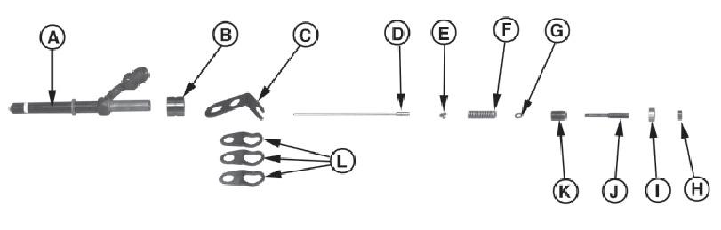
8.Attach spring seat (E), pressure adjustment spring (F), and washer (G) onto the set screw unit.
9.Hold the unit in a slanting position (do not drop the valve).
10.Attach the springs and set screw unit to the fuel injection nozzle unit. Be sure that the spring or valve seat are not shifted during assembly.
11.Screw the pressure set screw (K) by hand as far as possible, usually about 10 full rotations.
12.Adjust the nozzle according to “Testing the Fuel Injection Nozzles” on page218.
13.Install the stroke set screw lock nut (H) and pressure set screw lock nut (I) onto the set screw unit.


