1 minute read
HYDRAULICSYSTEMME12002 ValveStructure


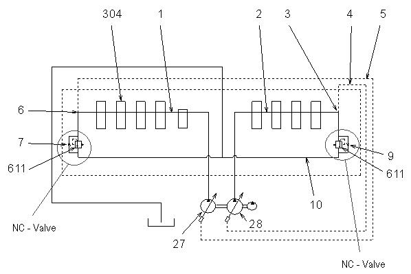
1System path
5,6Pump regulator canal
7Opening
10Tank line
611Pressure limiting valve
13Valve washer
14Spring
15Valve housing
102Casing
Pressure limiting valve (611) consists of valve washer (13), spring (14), valve housing (15), and casing (102). See Figure 3-88 and Figure 3-89.

Center bypass hydraulic fluid pressure increases path (3) pressure PN until the fluid arrives at the pre-set pressure of spring (14). When the fluid arrives at the pre-set pressure of spring (14), hydraulic fluid in path (3) opens valve washer (13) and flows into tank line (10). See Figure 3-88 and Figure 3-89.
In the unloaded state, rear pump (28) hydraulic fluid flows through path (2), opening (9) and tank line (10) to the tank. Opening (9) reduces all discharge, increasing path (3) pressure PN to maximum level and destroking rear pump (28). This minimizes rear pump (28) tilting angle and discharge. See Figure 3-88 and Figure 3-89.
Stand-by pump: approximately 6 gpm (21 L/min). Stand-by pressure: approximately 464 psi (32 bar).


