4 minute read
JOHNDEEREENGINE4045TF270(SNAC02633ANDUP)ME12002


3.Turn the radiator cap to the notch to release the pressure.
4.Remove the radiator cap.
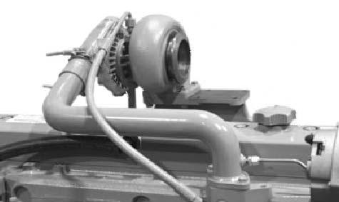
5.Remove exhaust elbow (A) at the air intake. See Figure 4-8.
NOTICE: The cylinder head is removed more easily if you remove the turbocharger without removing the exhaust bracket.
6.Disconnect the oil outlet and intake lines (B) from turbocharger (C). See Figure 4-8.
7.Remove turbocharger (C) and exhaust elbow (A). See Figure 4-8.
IMPORTANT:Always replace the cylinder head cover gasket if the cylinder head cover is removed when overhauling the engine or cylinder head.
8.Remove and retain the hexagon nuts and Orings from the cylinder head cover (D). Replace them if necessary. See Figure 4-8.
9.Remove the cylinder head cover (D). See Figure 4-8.
RemovingtheFuelLines, FuelFilter/WaterSeparator
3.Remove the fuel lines.
4.Remove fuel filter/water seperator (E) and the brackets if necessary. See Figure 4-10.
5.If installed, remove fuel pump (D). Check the front surface of the pump lever for wear. Replace the fuel pump if the surface is flat or concaved due to wear. See Figure 4-10.
6.(Optional) Remove the alternator to ease the work.

7.Remove the tube that connects the thermostat housing with coolant pump (C). See Figure 49.
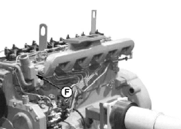
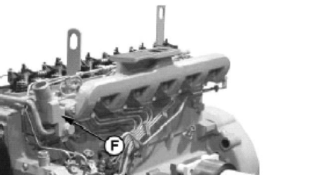
8.Remove fuel return line (F) and fuel feed lines (G) as a unit. See Figure 4-11.
9.Remove fuel injection nozzles (H). See Figure 4-11.
1.Remove exhaust bracket (A) using the guide pins. See Figure 4-9.
2.Remove the thermostat housing/coolant supplier unit (B). See Figure 4-9.
NOTICE: Loosen all rocker arm set screws before removing the unit.
RemovingtheCylinderHead
1.Remove the rocker arm unit. See Figure 4-12.
2.Remove the coolant temperature sensor connector line (A) from the fuel injection pump wiring harness. See Figure 4-13.
4.Clean and check the push rods.
5.Check the cylinder head bolts tightening torques.
If the cylinder head gasket is damaged, check and write down the cylinder head bolts tightening torques.
3.Remove all push rods. Write down the position of each push rod and organize them so that they are re-installed into the same position. See Figure 4-14.
6.Mark the surface of screw head (B) and cylinder head (C). See Figure 4-15.
7.Loosen the hexagon bolt by 1/2 rotation. See Figure 4-15.
8.Using a torque wrench, tighten the hexagon bolt until the lines are aligned with each other and write down the torque. See Figure 4-15.
9.Remove and discard all cylinder head bolts.
IMPORTANT:Do not re-use cylinder head bolts.
IMPORTANT:NEVER use a screwdriver or a crowbar between the cylinder block and the cylinder head to loosen the cylinder head gasket. The screwdriver or crowbar can damage the sealing surfaces of the cylinder head and the engine block.
5.Remove the rockers from the engine block. Record the position of each rocker and organize them so that they are re-installed into the same position.
6.Wash the rockers with a solvent.
7.Apply clean engine oil to the rockers.
8.Re-install the rockers into the same engine block positions.
9.Check the top surface for evenness and usability.
InstallingtheCylinderHead
10.Raise cylinder head (D) off of the block. If it is jammed, use a soft hammer to carefully apply soft blows to the cylinder head. See Figure 416.
CleaningtheCylinderHead
1.Remove sealing materials, rust, carbon deposits, and other foreign materials from the top surface. The sealing surface must be clean.
2.Use a screw tap to clean the threaded bores in the cylinder block.
3.Use compressed air to remove residual material and fluids from the screw bores.
4.Use compressed air to remove all loose foreign materials from the cylinders and top surface.
NOTICE: Remove all residual material from the rockers before re-assembling the engine.
1.Dip the ends of fuel pump push rod (A) into clean engine oil. See Figure 4-17.
2.Carefully install fuel pump push rod (A) into the cylinder block. See Figure 4-17.
3.If necessary, install two parallel pins (B) into the cylinder block positioning holes. See Figure 4-18.
NOTICE: Always check the cylinder head gasket thoroughly for quality and usability.
4.Place the new cylinder head gasket onto the cylinder head. Do not use any sealing compound: insert the seal as is (dry).
NOTICE: Only use new cylinder head bolts with a collared head.
TighteningtheHexagonBolts
1.Install and tighten all bolts to the specified tightening torques, follow the tightening order shown in Figure 4-20.
First tightening torque 74 lb.-ft. (100 Nm).
Second tightening torque 111 lb.-ft. (150 Nm). After 5 minutes, check that the tightening torque is 111 lb.-ft. (150 Nm).
TurnAngleMethod
1.Final angle of rotation, use JT05993 Torque Angle Gauge to tighten each bolt by a further 60°±10°. See Figure 4-21.
5.Use guide pins (C) to align the cylinder head onto the engine block. See Figure 4-19.
IMPORTANT:If the cylinder head is shifted while positioned on the engine block, the cylinder head gasket can be damaged.
6.Place the cylinder head onto the guide pins and lower it onto the cylinder block. See Figure 419.
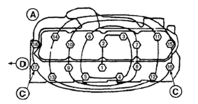
CHoles (for guide pins)
DFour-cylinder engine
EArrow to front of engine
7.Remove guide pins (C). See Figure 4-19 and Figure 4-20.
8.Obtain new cylinder head bolts with a collared head.
AlternateTurnAngleMethod
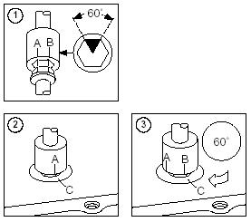
1.Make two marks (A and B) on the socket spanner that are 1/6 rotation (60° ±10°) apart. See Figure 4-22, 1.
InstallingthePushRods,RockerArmUnit
Rods
1.Install all push rods into the same position from which they were removed. See step 3 of “Removing the Cylinder Head” on page209. See Figure 4-23.
Figure 4-22 Alternate Turn Angle Method
2.Place the socket spanner onto the hexagon bolt. On cylinder head (C), make a mark aligned with the first mark (A) on the hexagon bolt. See Figure 4-22, 2.
3.Tighten all hexagon bolts, in the order shown in Figure 4-20 on page 211, until the second mark (B) on the socket spanner is aligned with mark (C) on the cylinder head as shown. See Figure 4-22, 3.
NOTICE: Tightening the cylinder head bolts is not necessary after running the engine if the collar screws have been tightened as specified.
2.Install the coolant temperature sensor connector line (A) to the fuel injection pump wiring harness. See Figure 4-24.
InstallingtheFuelLines,FuelFilter/Water Separator
5.If removed, install fuel pump (G). See Figure 4-28.
6.Install fuel filter/water seperator (H) and brackets if necessary. See Figure 4-28.
7.Install fuel lines.
8.Install thermostat housing/coolant supplier unit (E). See Figure 4-27.
9.Install exhaust bracket (D) using the guide pins. See Figure 4-27.
InstallingtheCylinderHeadCover
1.Install fuel injection nozzles (C). See Figure 426.
2.Install fuel return line (A) and fuel feed lines (B) as a unit. See Figure 4-26.
3.Install the tube that connects the thermostat housing with the coolant pump (F). See Figure 4-27.
4.(Optional) If the alternator was removed (see step 6 on page208), install the alternator.
1.Install cylinder head cover (D). See Figure 429.
2.Install hexagon nuts and O-rings onto the cylinder head cover (D). See Figure 4-8.
3.Install turbocharger (C) and exhaust elbow (A). See Figure 4-29.
4.Connect oil return and intake lines (B) to turbocharger (C). See Figure 4-29.
5.Install exhaust elbow (A) at the air intake. See Figure 4-29.
6.Install the radiator cap.
7.Add radiator coolant.


