2 minute read
HYDRAULICSYSTEMME12002


531Pivot point
532Servo pistons
611Lever linkage system
613Regulator body
621Pilot pistons
625Outer power springs
626Inner power springs
643Pilot pistons
646Control springs
652Main spools
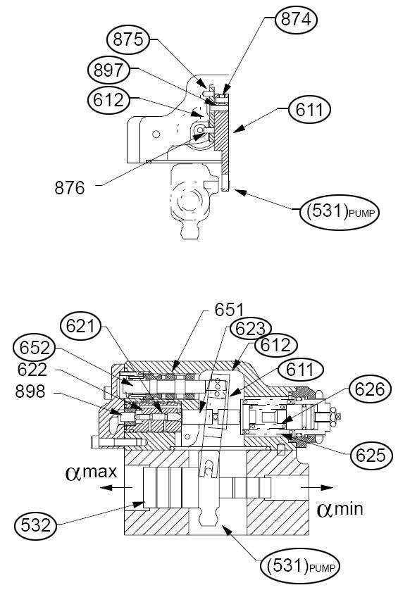
Pump regulator operation uses a lever linkage system (611) that connects servo pistons (532), main spools (652) and regulator body (613). See Figure 3-20.
Pilot pistons (621 and 643) and control springs (625, 626 and 646) activate the lever linkage system (611). The lever linkage system (611) ensures a highly responsive and accurate control system. See Figure 3-20.
Pivot point (531) connects servo piston (532) to pump swash plate (212). See Figure 3-20 for servo piston (532) and pivot point (531), and Figure 3-19 for swash plate (212).
Moving servo piston (532) to the left increases pump displacement and moving servo piston (532) to the right decreases pump displacement. See Figure 3-20.
Servo piston (532) has an area ratio of 4:1. The smaller diameter area on the right side of the servo piston is continuously connected to the pump's outlet pressure. The larger diameter area on the left side of the servo piston (532) is fed from the main regulator spool (652). As the main regulator spool (652) pressurizes the left side of the servo piston, it continuously reduces the pump displacement. See Figure 3-20.
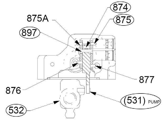
531Pivot point
532Servo piston
874Fixed pivot
875Fixed pivot pin
897Feedback pivot
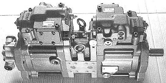
Regulator assembly lever and linkage arrangements are shown in Figure 3-21.
The main feedback lever is shown in the center of the pump where servo pivot (531) connects it to servo piston (532). See Figure 3-21.
Fixed pivot (874) connects main feedback lever to main spool (652). Feedback pivot (897) connects main feedback lever to displacement lever (right side) and power lever (left side). Fixed pivot pin (875) secures displacement lever (right side) to the regulator body, and fixed pivot (874) secures power lever (left side) to the regulator body. See Figure 3-21.
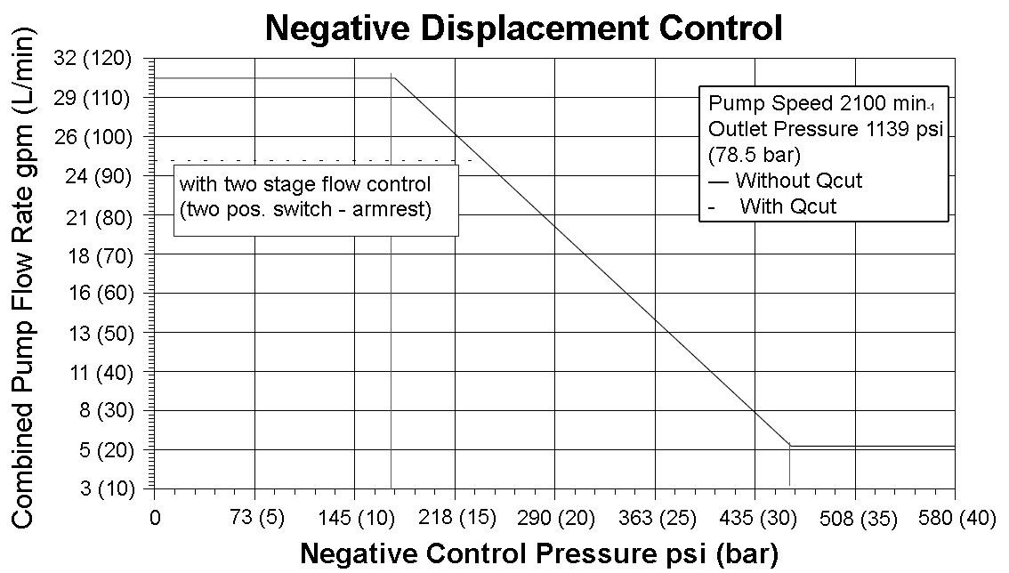
HydraulicPumpRegulatorPerformanceDiagrams
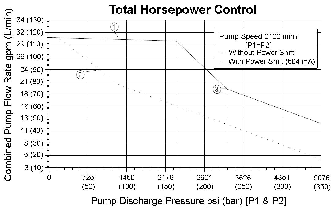
1.Oil
2.Poteniometer changed oil flow.
3.Spring 2 - regulation starts.
The regulator consists of two separate halves:
•Power or Torque Summation Control (left side)
•Negative Displacement Control (right side)
531Pivot point
532Servo piston
611Lever linkage system
612Power control lever
613Regulator body NC system
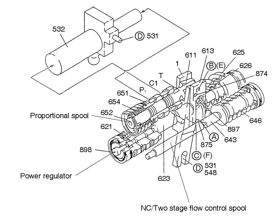
621Regulator piston - power regulator
622Housing - power regulator
623Piston rod - power regulator
625Outer power springs
626Inner power springs
643Piston rod -NC regulation
646Spring - NC regulation
651Spool housing
652Main Spool
531Servo
Power push rod (623) forces output pressure from variable pump 1 into the larger stepped diameter area of power control piston (621). Power push rod (623) forces return output pressure from variable pump 2 into the smaller stepped diameter area of power control piston (621). See Figure 3-25 and Figure 3-26.
Because these two stepped areas are equal, both pumps counter-stroke to the same displacement rate. The inner (626) and outer (625) power springs create a spring preload that balances the force produced. See Figure 3-25.
When return output pressure is low, only outer spring (625) is active. When increased output pressure from both pumps is forced into power control piston (621), outer spring (625) and inner spring (626) are both active. The change in spring rate provides the characteristic curve. See Figure 3-25.
Because of pump(s) pressure forces, power push rod (623) presses against outer power springs (625), and this action moves piston (621). Piston (621) movement presses power control lever (612), located on fixed pivot (875), to the right toward outer power springs (625). Power control lever (612) uses feedback pivot (897) to transmit movement to feedback lever (611). Feedback lever (611) rotates “clockwise” (to the right) around servo pivot (531). See Figure 3-25.
Fixed pivot (874) connects feedback lever (611) to main spool (652). Because of this connection, main spool (652) transports pressurized oil to the larger diameter area of servo piston (532). This counterstrokes the pump and rotates main feedback lever (611) “counter-clockwise” (to the left). See Figure 3-25.
When servo piston (532) position and pump displacement maintains main spool (652) in a central metering position, a state of equilibrium exists. In this central metering position, pressure forced into the larger diameter area of servo piston (532) maintains equilibrium. See Figure 3-25.


