3 minute read
RegenerationCircuit


Figure 3-121 Regeneration Circuit
Return flow from the head side of boom cylinder (1) separates at line (44). A portion of this flow opens check valve (14), check valve (47), and then passes through path (34) in boom spool (303). See Figure 3-121, and for boom cylinder (1) only, see Figure 3-111 on page119.
Because boom spool (303) is in the left position, path (48) pressure flows into return path (15), relieving spring chamber (39) pressure. Path (34) hydraulic fluid forces check valve (47) and check valve (14) to the right against spring (38) and spring (49). See Figure 3-121.
Hydraulic fluid flows through path (36) and port (4) into the rod side of boom cylinder (1). See Figure 3-121, and for boom cylinder (1) only, see Figure 3-111 on page119.
While lowering the boom, the boom 1 spool (303) regenerative circuit function transfers flow from the head side to the rod side. See Figure 3-121.

When the control lever returns to the neutral position, pilot pressure through port (23) is cut-off and spring (322) and spring (328) returns boom spool (303) to neutral position. See Figure 3-121 and Figure 3-122.
Path (43) shuts-off, intercepting the flow from path (44) to path (34). See Figure 3-121.
Spring (49) shuts-off check valve (14) and spring (38) presses check valve (47) to the left. See Figure 3-121.
Figure 3-122 Raising the Boom
For a larger view of Figure 3-122, see Figure 3-117 on page122.
Figure 3-123 Negative Control During the Regeneration Operation
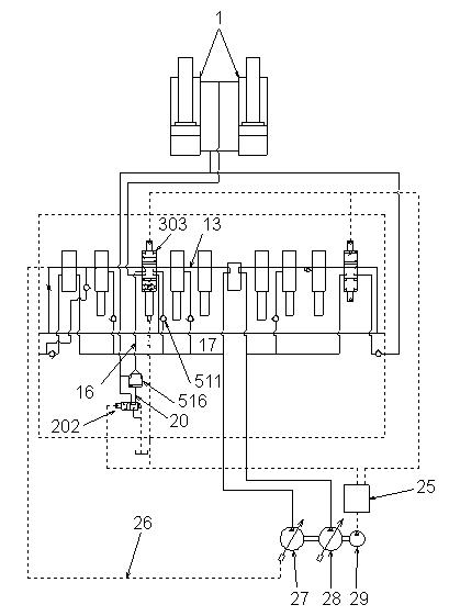
The regeneration function saves hydraulic fluid that flows from front pump (27) into the rod side of the boom cylinder (1). While lowering the boom, higher negative control pressure decreases front pump (27) discharge. See Figure 3-124.
FullOperationCase
Hydraulic fluid in front pump (27) flows from center bypass (13) through the slightly-opened path (33) and into center bypass (11). The hydraulic fluid serves as the negative control signal pressure when, to decrease discharge from front pump (27), it flows through line (26) and into the front pump regulator. See Figure 3-123 and Figure 3-124.
FineMeteringOperationCase
Spool (303) is positioned slightly to the left, path (46) and path (43) are slightly open and path (31) is shut-off. Return flow from path (44) flows through path (43) and path (34), forces open return check valve (41), and flows through path (42) and into return path (15). See Figure 3-123.

Hydraulic fluid from center bypass (13) flows through the partially opened path and into center bypass (11). Hydraulic fluid flows through partial path (33) and into center bypass (11). Higher negative control pressure decreases discharge from front pump (27), slowing cylinder movement. See Figure 3-123 and Figure 3-124.
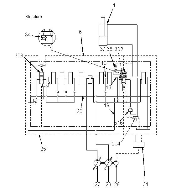
Figure 3-124 Boom Structure
For a larger view of Figure 3-124, see Figure 3-109 on page118.
DipperArmSection
1Dipper arm cylinder
6 Pilot pressure hose (cylinder rod side)
10Bypass
16Direct piloted check valve
19Summation line
20Tank line
25 Pilot pressure hose (cylinder bottom side)
27Variable axial piston pump 1
28Variable axial piston pump 2
29Gear pump
31Pilot oil supply unit
34Regeneration function
37, 38 Bypass valve (for regeneration valve)
204, 516 Leakage free valve - spool dipper arm
302Spool section 1
308Spool section 2
Functions:
•Summation (bottom and rod side)
•Direct piloted check valve
•Regeneration function dipper arm cylinder bottom side
DipperArmSection(1)
DipperArmSection(2)
1,6 Pilot pressure port - dipper arm cylinder rod side
2 Piloted lekage free valve - spool dipper arm
3,8Direct piloted check valve
4Bypass valve
5Spool
7 Secondary pressure limiting valve with suction function
9 Pilot pressure port - dipper arm cylinder bottom side
10Dipper arm cylinder bottom side
11Regeneration valve
1 Pilot pressure port for function side valve block
2,3Direct piloted check valve
4Port summation line
5 Pilot pressure line - dipper arm cylinder extending
6 Pilot pressure line - dipper arm cylinder retracting
7Shuttle valve

8Spool

Spool arm 1 (302) and spool arm 2 (308) both operate when extending and/or raising the dipper arm. Hydraulic fluid from front pump (27) and rear pump (28) combine and flow into the arm cylinder. See Figure 3-128 and Figure 3-129.
Arm lock valve (204, 516) is included with the dipper arm control. When the control lever is in the neutral position, it shuts-off the return flow from the rod side of cylinder (1) and prevents the arm from lowering because of leakage from arm spool (302). See Figure 3-128 and Figure 3-129.
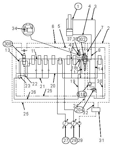
The construction and operation of arm lock valve (204, 516) are the same as those of boom lock valve (202, 516). See “Lowering the Boom” on page123.
For a larger view of Figure 3-129, see Figure 3-109 on page118.


