5 minute read
HYDRAULICSYSTEMME12002


P1andP2Constant,Connected,Loaded
Figure 3-27 P1 and P2 Constant, Connected, and Loaded
Balanced condition prerequisites: P1 and P2 are constant, with no regulation function, and are connected and loaded at the same delivery pressure.
P1 is connected to the front pump delivery port and P2 is connected to the rear pump delivery port. See Figure 3-27.
During the balanced condition:
•Power piston force is balanced against the power spring pack force.
•Main spool (652) metering position is in a null position. See Figure 3-27.
•Main spool (652) transports enough fluid to the larger stepped diameter area of power control piston (621) to maintain a power piston force balance across the servo piston (532). See Figure 3-27.
•The larger diameter area on the left side of the servo piston (532) pressure is approximately one-fourth (¼) of the pumps total delivery pressure. See Figure 3-27.
Feedback lever (611) maintains the swash plate (212) position, and moves main spool (652). Write
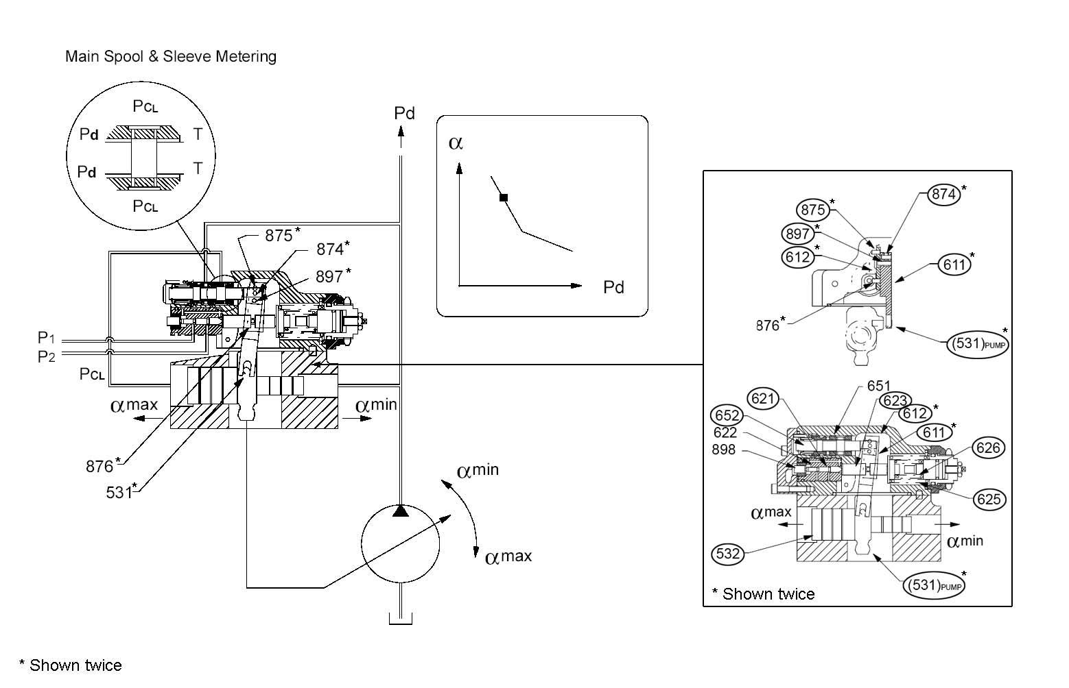
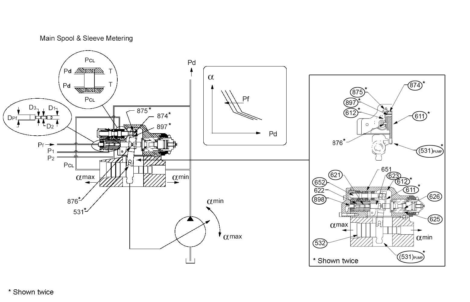
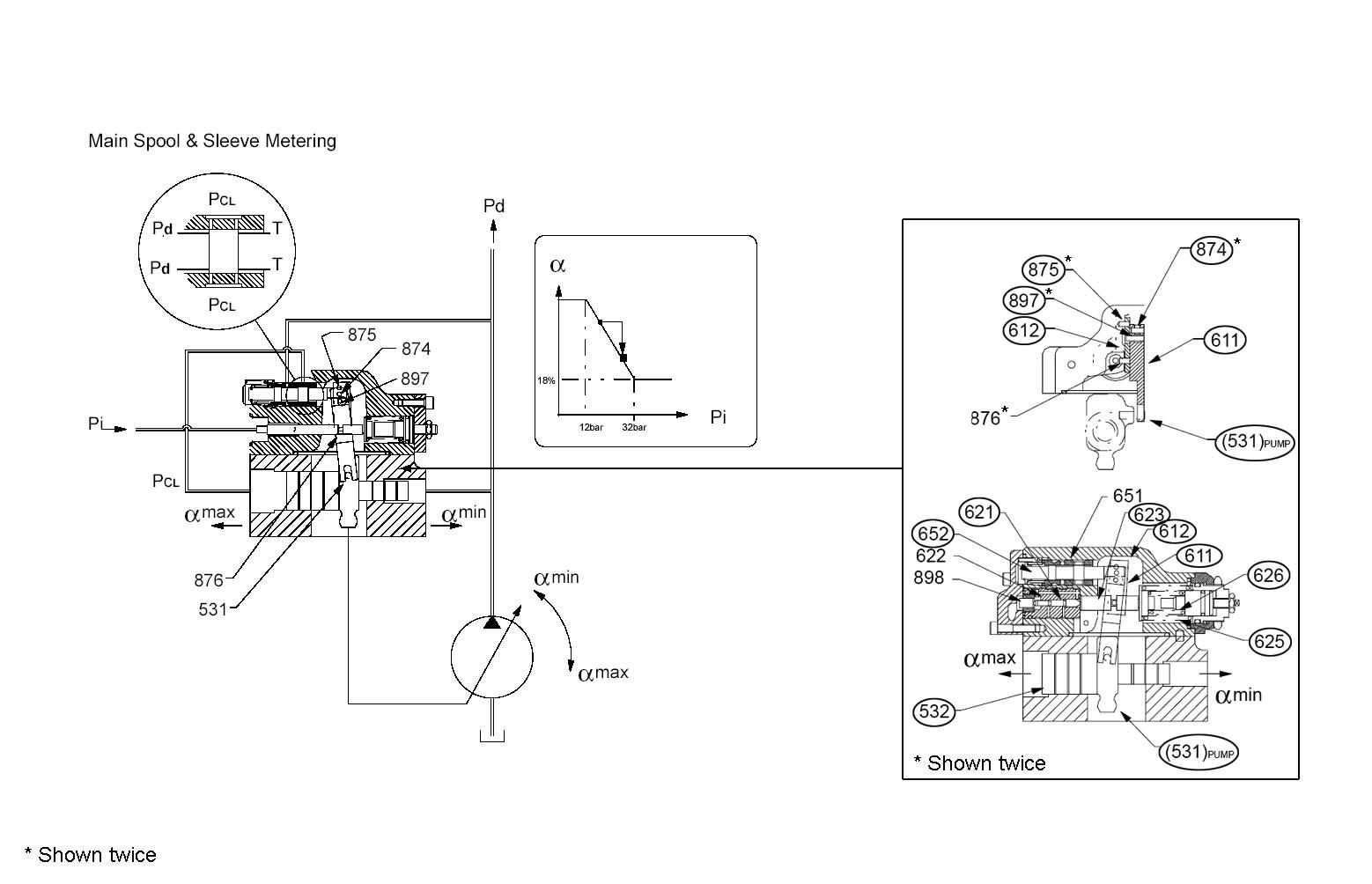
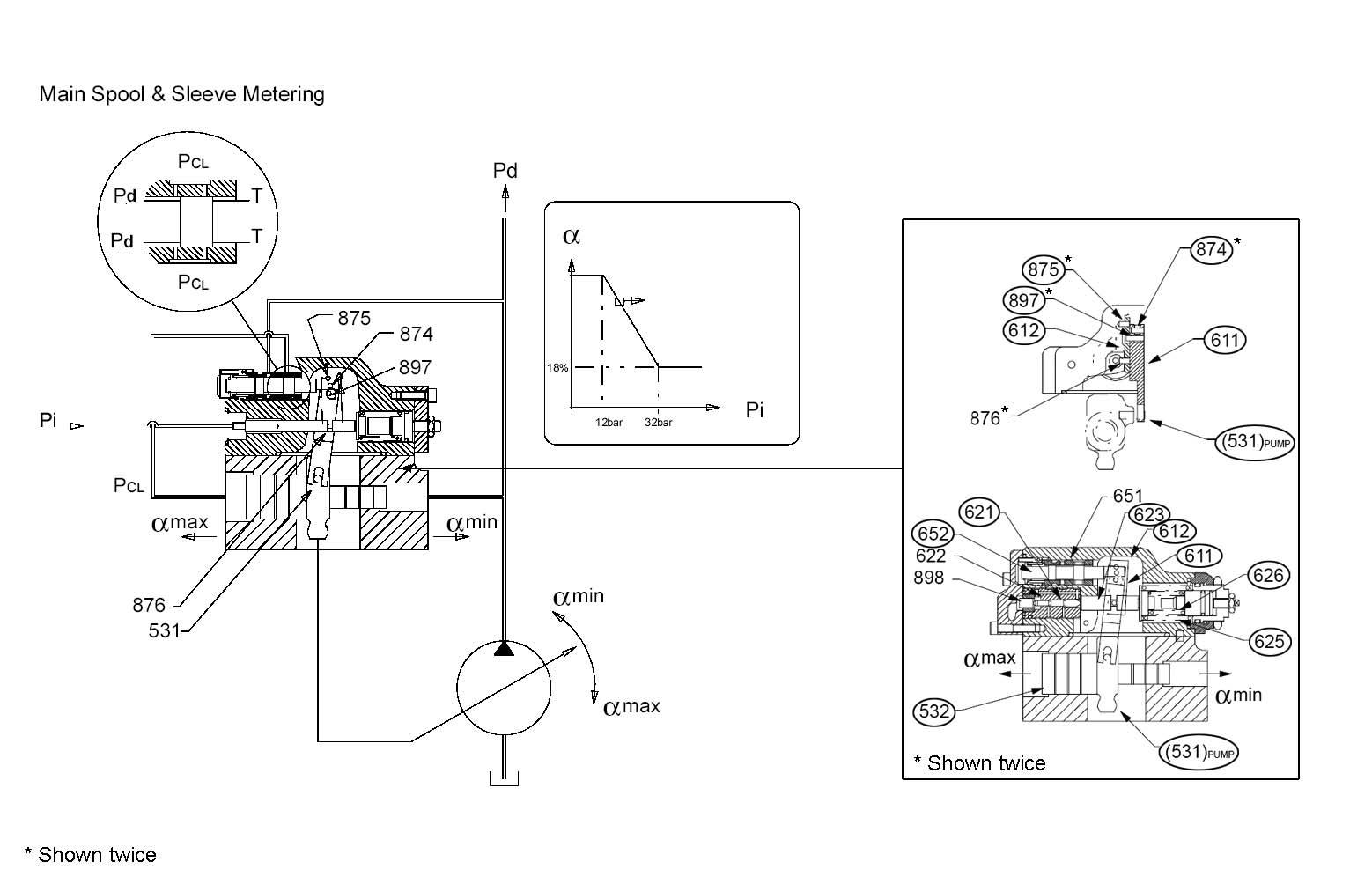
Figure 3-28 Main Spool and Sleeve Metering
While P1 and P2 delivery pressure increases, power control piston (621) compresses power spring pack (inner [626] and outer [625] spring). Power push rod (623) linear movement causes the power control lever (612) to pivot around fixed pivot 1 toward the left. See Figure 3-28.
Power control lever (612) uses feedback pivot (897) to transmit movement to feedback lever (611). See Figure 3-28.
Feedback lever (611) rotates “clockwise” (to the right) around servo pivot (531), causing main spool (652) to rotate to the right through the spool pivot point. See Figure 3-28.
Main spool (652) metering forces delivery pressure into the larger diameter area on the left side of the servo piston (532) (i.e. Pd to PCL). See Figure 328.
PumpOilFlowDrops
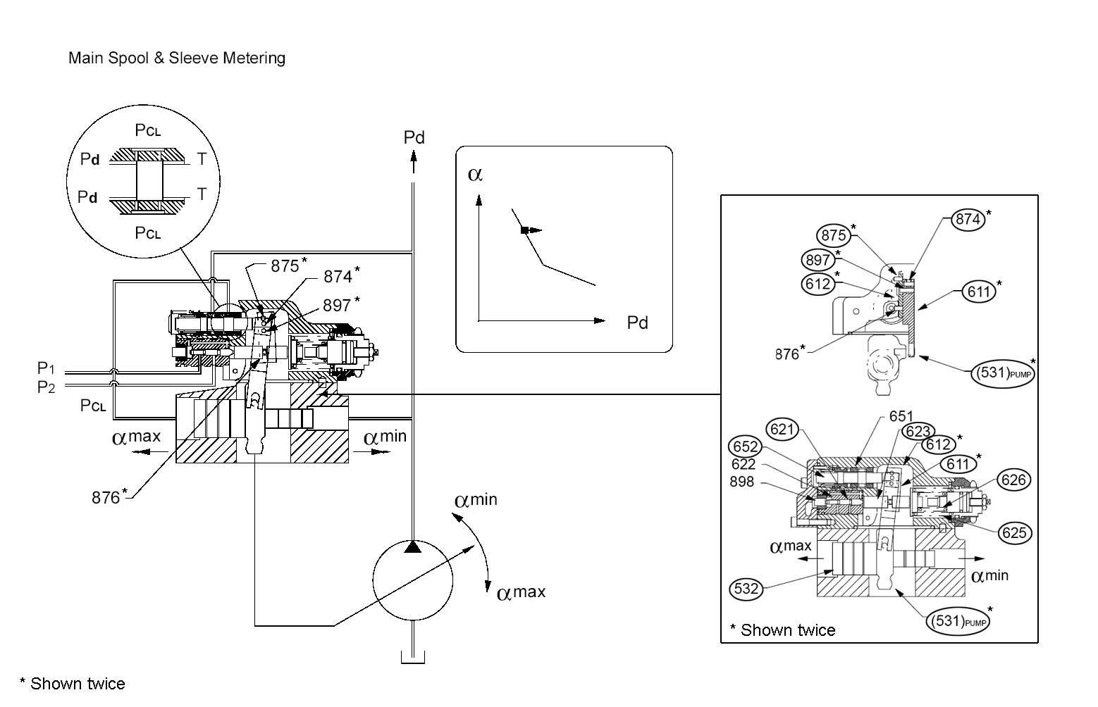
Figure 3-29 Pump Oil Flow Drops
When pump oil flow drops, servo piston (532) moves to the right toward minimum displacement. As servo piston (532) moves to the right, feedback lever (611) rotates around feedback pivot (897), causing main spool (652) to return to the null position (left of its previous position). See Figure 3-29. Main spool (652) transports enough fluid to maintain the pressure balance across servo piston (532) and pump swash plate. See Figure 3-29.
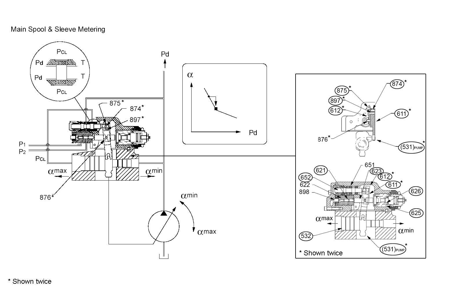
Figure 3-30 P1 or P2 Decreases, the Oil Flow Increases
While P1 and/or P2 pressure decreases, delivery pressure decreases. This decrease causes power spring pack (inner [626] and outer [625] spring) to shift power push rod (623) to the left while reducing the power piston force. See Figure 3-30.
Feedback pivot (897) and main spool (652) compression spring transmit power lever (left side) movement. Main spool (652) compression spring also eliminates feedback by pulling main spool (652) to the left. Main spool (652) movement to the left meters the larger diameter area on the left side of the servo piston (532) pressure to the tank pressure. Because the small side of the servo piston (532) is connected to the pump delivery pressure, when servo piston (532) moves to the left, pump displacement increases toward maximum. See Figure 3-30.
After servo piston (532) moves to the left and reaches its final position, feedback lever (611) shifts main spool (652) to the null position, restoring equilibrium. See Figure 3-30.
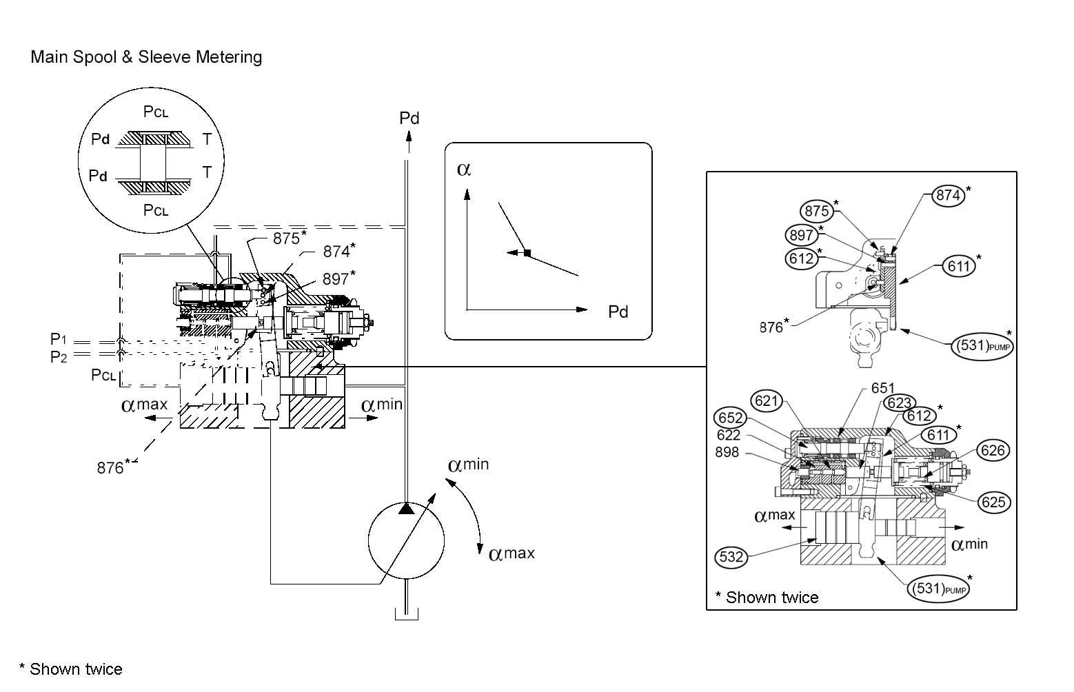
Figure 3-31 Variable Horsepower Control
Pump P2 performance can change because of a potentiometer in the cabin.
Power control piston (621) contains an additional piston (898), supplied by a proportional pressure reducing valve. Its pressure (Pf) is applied to the D3 piston diameter with the effect of changing the effective spring preload of the inner (626) and outer (625) power springs. See Figure 3-31.
Apply this pressure (Pf) to shift the torque summation setting. Increasing the applied pressure (Pf) decreases the effective spring preload available and its torque setting.
Power shift control is used so that a machine can operate at lower engine speeds without stalling the engine.
Figure 3-32 Negative Displacement Control and Feedback Mechanisms
Negative control pressure presses against the rightend of the displacement piston and push rod (643). Displacement pilot spring (646) balances the force produced. See Figure 3-32.
Any force imbalance moves displacement control lever against fixed pivot (875). If displacement piston and push rod (643) move to the right, displacement control lever uses feedback pivot (897) to transmit pressure to feedback lever (611). Feedback lever (611) then rotates slightly “clockwise” (to the right) around servo pivot (531). See Figure 3-32.
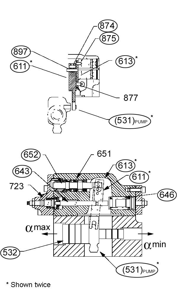
Fixed pivot (874) connects feedback lever (611) to main spool (652), causing main spool (652) to meter pressurized fluid into the larger diameter area on the left side of the servo piston (532). Fluid entering the larger diameter area of the servo piston (532) counter-strokes the pump. Feedback lever
(611) then rotates slightly “counter-clockwise” (to the left) around servo pivot (531). See Figure 3-32.
After servo piston (532) and pump displacement stabilize, main spool (652) returns to the central metering position. After main spool (652) returns to the central metering position, pressure shifts to the larger diameter area on the left side of the servo piston (532), restoring equilibrium. See Figure 332.
Figure 3-33 Pressure P1 is Connected to Negative Control Pressure Signal
When displacement piston force is balanced against displacement spring force, main spool (652) metering is in a null position. Main spool (652) metering also transports enough fluid to the larger diameter area on the left side of the servo piston (532) to maintain a balanced force across the servo piston (532). See Figure 3-33.
During the balanced condition, the larger diameter area on the left side of the servo piston (532) pressure is approximately one fourth (¼) of the pumps total delivery pressure. See Figure 3-33.
Feedback lever (611) maintains the swash plate (212) position, and this moves the main spool (652) which corrects any error. Write down the lever and piston positions. See Figure 3-33.
NCValvePressureIncreases,PumpOilFlowRateDecreases
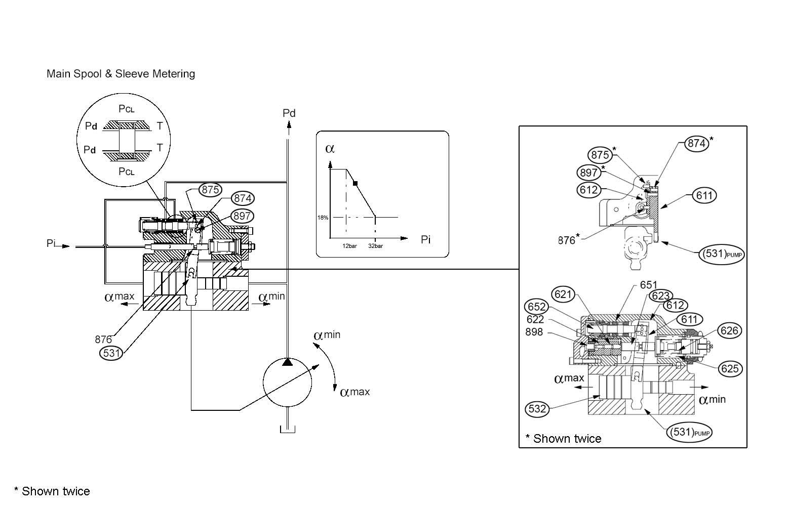
Figure 3-34 NC Valve Pressure Increases, Pump Oil Flow Rate Decreases
When the negative pressure control signal (Pi) increases, the displacement piston compresses the displacement spring. The linear movement of the displacement piston pivots the displacement lever around fixed pivot 1, toward the left. See Figure 334.
The displacement lever uses feedback pivot (897) to transmit movement to feedback lever (611). See Figure 3-34.
Feedback lever (611) rotates “clockwise” (to the right) around servo pivot (531), causing main spool (652) to rotate to the right through the spool pivot point. See Figure 3-34.
Main spool (652) metering transports delivery pressure to the larger diameter area on the left side of the servo piston (532) (i.e. Pd to PCL). See Figure 3-34.
Figure 3-35 Power Regulator in Neutral Position, Lower Flow Rate
When the power regulator is in neutral position, pump oil flow drops and servo piston (532) moves to the right, toward minimum displacement. As servo piston (532) moves to the right, feedback lever (611) rotates around feedback pivot (897), causing main spool (652) to return to the null position (left of its previous position). See Figure 3-35.
Main spool (652) transports enough fluid to maintain the pressure balance across servo piston (532), and swash plate (212) moves to a new position. See Figure 3-35.
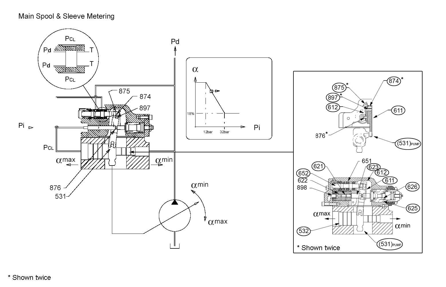
Figure 3-36 Negative Control Valve Pressure Decreases, Pump Oil Flow Rate Increases
Negative control pressure decreases and releases the displacement spring. The piston moves to the left of its previous position and the control pressure decrease reduces piston force displacement. See Figure 3-36.
Feedback pivot (897) and main spool (652) compression spring transmit power lever (left side) movement. Main spool (652) compression spring eliminates feedback by pulling main spool (652) to the left. Main spool (652) movement to the left meters the larger diameter area on the left side of the servo piston (532) pressure to the tank pressure. Because the small side of the servo piston (532) is connected to pump delivery pressure, when servo piston (532) moves to the left, pump displacement increases toward maximum. See Figure 3-36.
After servo piston (532) moves to the left and reaches its final position, feedback lever (611) shifts main spool (652) to the null position, restoring equilibrium. See Figure 3-36.


