1 minute read
ME12002HYDRAULICSYSTEM


into the tilt bushing (214) and swash plate (212) assembly. See Figure 3-19.
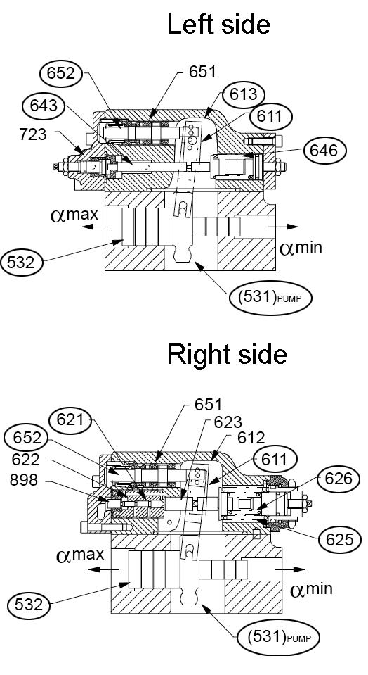
Pump regulator pressure applied to either end of servo piston (532) causes linear movement of servo piston (532). See “Hydraulic Pump Regulator Functions” on page69. This linear movement presses tilting pin (531) into swash plate (212), forcing swash plate (212) to move angularly. This angular movement varies the pump tilting/swash angle. See Figure 3-19.
Use screw adjusters and lock nuts to adjust the maximum (954) and minimum (953) tilting angle settings. See Figure 3-19.
ValveCoverGroup
Valve cover group consists of the following parts. See Figure 3-19 for identification.
Valve cover(312)
Valve plate(313)
Valve plate pin(885)
Valve plate (313) and its two “melon” shaped ports are installed onto valve plate (313). Valve plate (313) is located next to valve plate pin (885). See Figure 3-19.
These ports transport oil to and from cylinder block (141). Valve plate (313) controls the oil passage port used and valve cover (312) connects the ports to the externally piped suction and outlet pressure ports. See Figure 3-19.
When drive shaft (111) rotates, cylinder block (141) also rotates because it is spline-coupled to drive shaft (111). Because shoe (152) is attached to swash plate (212), if swash plate (212) is tilted, pistons (151) arranged in cylinder block (141) rotate when cylinder block (141) rotates. Cylinder block (141) moves forward and rearward once per revolution.
Piston (151) rotates away from valve plate (313) for the first half of the rotation (suction stroke) and rotates toward valve plate (313) for the second half of the rotation (oil delivery stroke).
The larger the swash plate (212) tilt angle, the longer the piston (151) stroke, and the higher the displacement. If the swash plate (212) tilt angle is zero, piston (151) makes no stroke and delivers no oil.
Coupling (114) within central valve block (312) connects the two pumps and their individual regulators together. Coupling (114) also connects drive shaft (111) on the front pump to the prime mover. The front and rear pumps share a common oil suction port, but contain independent delivery ports.
HydraulicPumpRegulatorFunctions
Hydraulic pump regulator functions include:
•Summation power control
•Variable power shift (potentiometer controlled)
•Negative control regulation (NCR)
•Two stage maximum flow control (two stage switch)


