1 minute read
HYDRAULICSYSTEMME12002


TestingHydraulicPressure
Overview:
•One two-step primary-pressure limiting valve for pump P1+P2 (main valve block).
•The side valve block is supplied by pump P1 through the main valve block.
•One primary-pressure limiting valve at the side valve block (attach: pressure adjustment).
•Measuring points at the hydraulic pump (P1, P2) and at side valve block (P3) of the pilot oil supply unit.
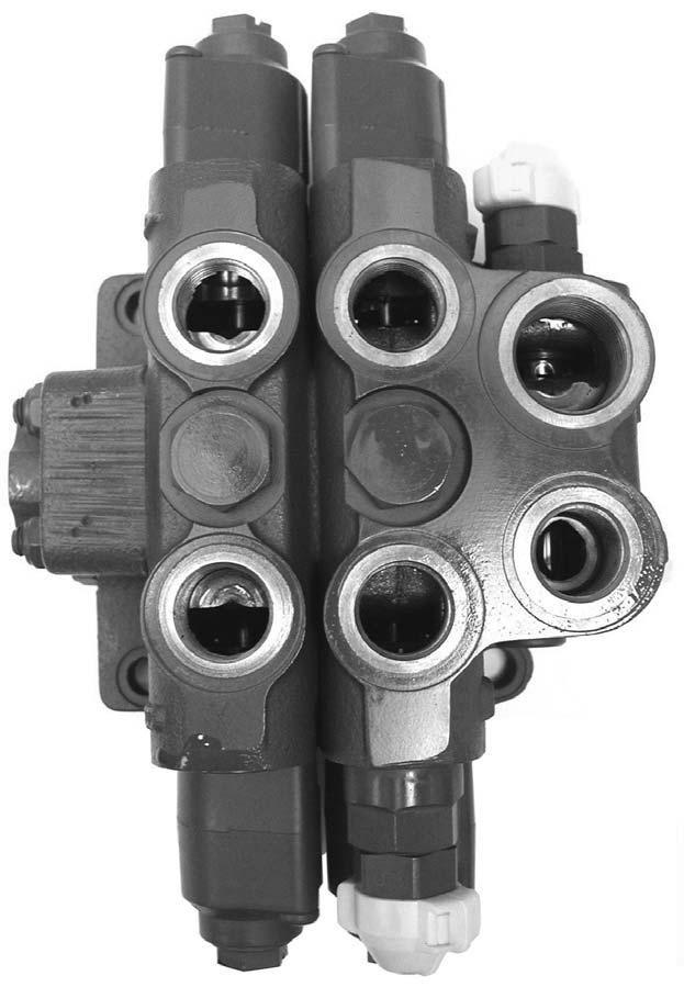
CheckingtheSideValveBlock(PPLV-2)

PressureSetting
TestingSideValveBlock(P1)Pressure
Functions: Dozer blade cylinder and boom offset cylinder.
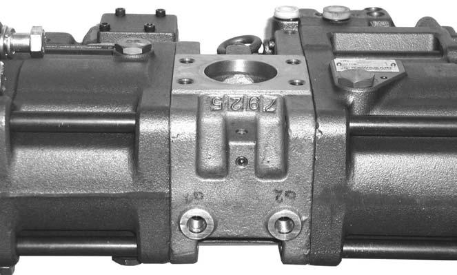
Measuring Points (MP1, MP2) (photo taken from underneath)
1.Apply pressure gauge at measuring point MP1 and MP3. See Figure 3-15 and Figure 3-16.
2.Full throttle, raise the boom all the way up.
3.Increase the primary pressure limiting valve 1setting PPLV-1 (MR) up to 5076 psi (350 bar) (main valve block - with adjustment screw e1 at the main relief valve).
PPLV-2PressureDrop
Example:
System pressure at full throttle = 4351 psi (300 bar)
System pressure at minimum throttle = 4061 psi (280 bar) => OK (low limit approximately 3844 psi [265 bar])
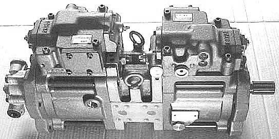
PressureTestingHydraulicPumpP1(A1) andP2(A2)
Functions: Boom, dipper arm, bucket, drive, auxiliary hydraulics, and swivel.
CheckingtheDrivePressure
1.Activating the drive function increases the main pressure limiting valve setting internally to 4641 psi (320 bar) (MR=4351 psi [300 bar]) by using the pilot pressure (port PP).
CheckingtheAuxiliaryHydraulicsPressure
4.Check the pressure at measuring point (MP3), and if necessary, adjust the primary pressure limiting valve at the side valve block PPLV-2. See Figure 3-16 and Figure 3-17.
5.Adjust the primary-pressure limiting valve PPLV-1 (MR) back to its original setting (main valve block). See “Hydraulic System Specifications” on page7.
CheckingthePressureDrop
1.Raise the boom all the way up, at full throttle.
2.Reduce the throttle quickly from maximum to minimum, while holding the boom all the way up.
3.Check the pressure drop. The pressure drop should not exceed more than 10% of the setting (approximate value only applicable to primary pressure limiting values). An excessive pressure drop might indicate leakage. Refer to the following table:
1.If the secondary pressure limiting valve (shock valve) settings are adjusted lower than the main pressure limiting valve (MR), measuring point MP1 measures auxiliary hydraulics secondary pressure limiting valve (shock valve) settings.
2.With ball valve opened, measuring point MP1 measures auxiliary hydraulics stored system pressure by tracking unpressurized return flow.
CheckingtheSwivelPressure
1.Measuring point MP2 measures swivel motor secondary pressure limiting valve (shock valve) settings because of their lower setting level. See “Hydraulic System Specifications” on page7.
CheckingthePrimary-pressureLimitingValve 1(MR)Setting
1.Apply gauge at measuring points MP1 and MP2.
2.Extend the dipper arm (cylinder bottom side) all the way, at full throttle.
3.Check and write down the pressure.


