2 minute read
HYDRAULICSYSTEMME12002


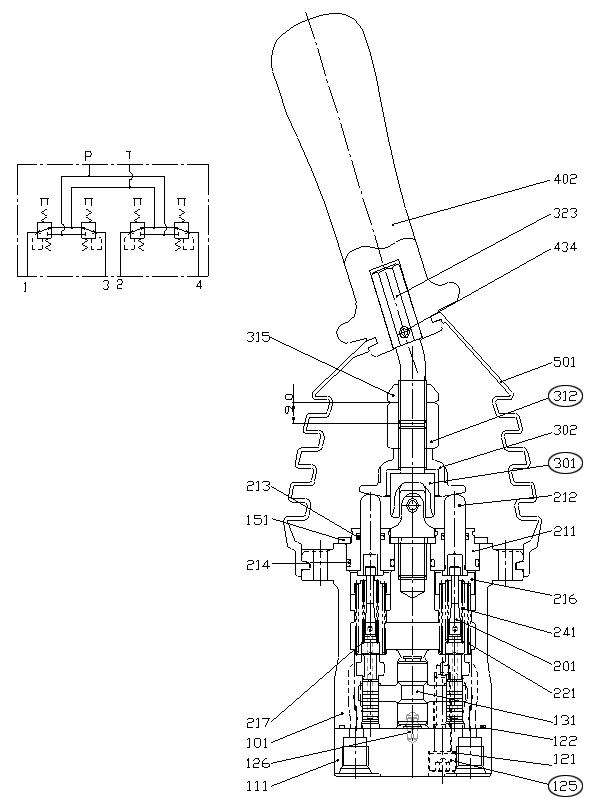
AssemblingtheJoystick
3.Write down the fitting position so that spring pin (126) can be inserted into the casing opening.
4.Tighten hexagon bolt M8 (125) to tightening torque 15.2±1.1 lb.-ft. (20.6±1.5 Nm). See Figure 3-193.
IMPORTANT:The surface of spool (201) and spring (216) can be damaged because of mishandling. Do not damage the surface of spool (201) while removing spool (201) and do not push spring (216) seating downward more than 1/4” (6 mm).
1.Install bushing (131) and O-ring (122) into casing (101). See Figure 3-191.
216217241
2.Install port plate (111) onto casing (101) using hexagon bolts M8 (125) and seal washers (121). See Figure 3-192 and Figure 3-193.
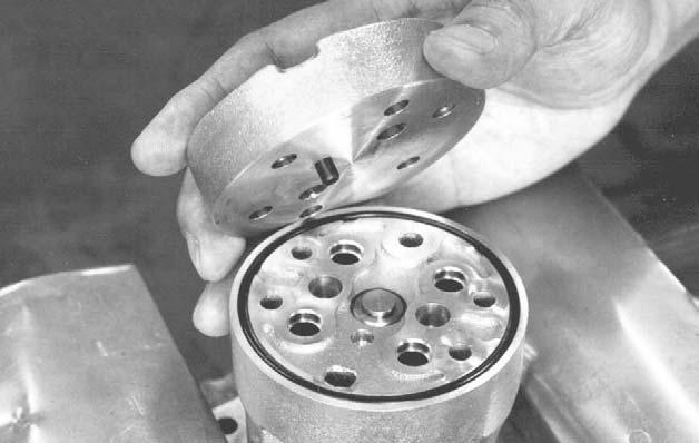
IMPORTANT:Replace seal washers (121) with new seal washers (121).
NOTICE:Steps 5-7 must be installed in order.
5.Install washer #2 (217) onto spool (201). See Figure 3-194.
6.Install secondary spring (241) onto spool (201). See Figure 3-194.
7.Install spring seating (216) onto spool (201). See Figure 3-194.
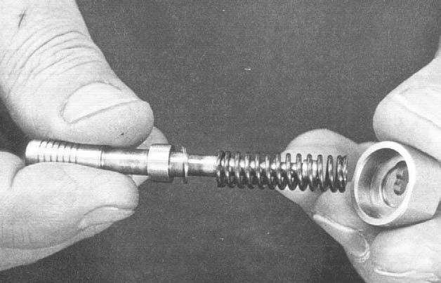
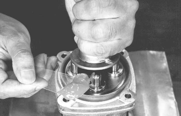
8.Press down spring seating (216) to flex the secondary pressure spring (241). At the same time, slide spring (241) sideways through the larger opening to attach it to spool (201). See Figure 3-195.
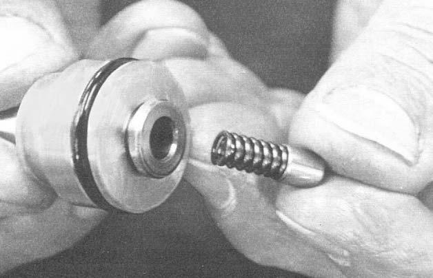
10.Install O-ring (214) onto plug (221). See Figure 3-197.
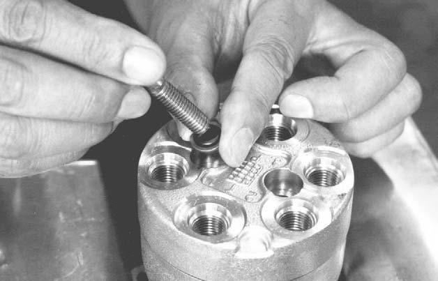
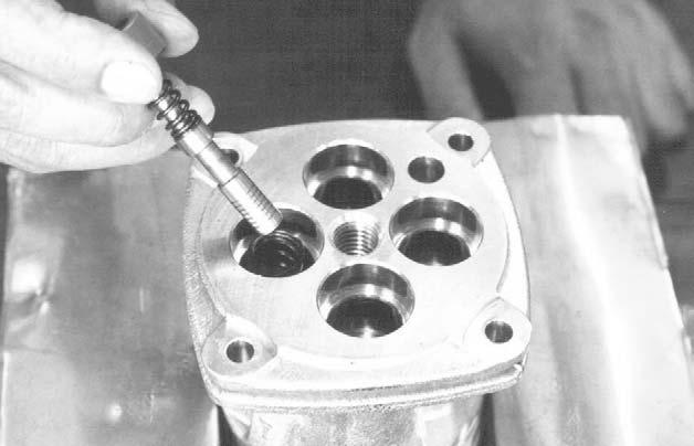
9.Install return spring (221) into casing (101). Do not press the spring seating down more than 1/4” (6 mm). See Figure 3-196.
NOTICE:Follow the installation sequence written down during step 15 of “Disassembling the Joystick” on page155 when installing the reduction valve assembly, steps 10-16, into casing (101).
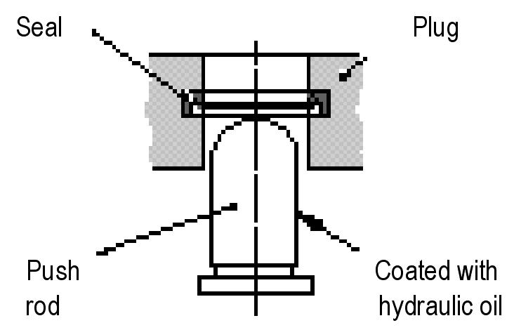
11.Insert seal (213) into plug (211) as shown. See Figure 3-198.
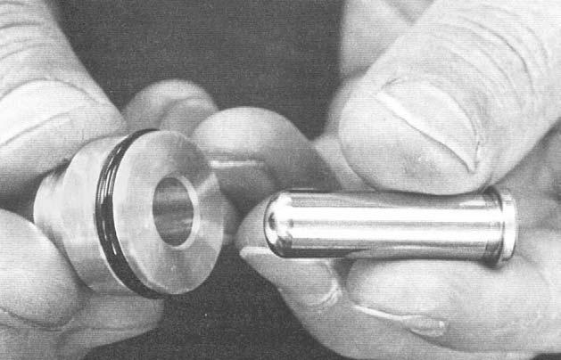
12.Install push-rod (212) into plug (211). See Figure 3-199.

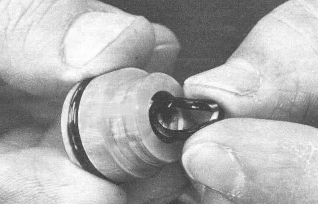
13.Install secondary spring (246) and spring seating (218) into push-rod (212). See Figure 3200.

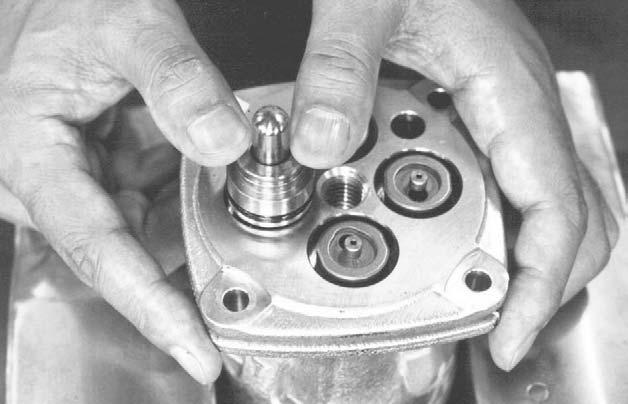
15.Install the plug assembly into casing (101) as shown. See Figure 3-202.
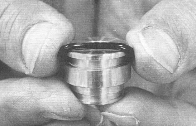
14.Apply hydraulic oil to the surface of push-rod (212). See Figure 3-201.
Warning
ITEMSUNDERTENSION:Plugassemblyand plate(151)mustbeassembledagainstspring tension.Besurespring(221)doesnotlaunch fromtheunit,becausethismaycausedamage and/orseriousinjury.
Caution
ITEMSUNDERTENSION:Thesurfaceofspool (201)andcasing(101)canbedamaged becauseofmishandling.Donotdamagespool (201)orcasing(101)duringassembly.
16.Insert all return spring (221) simultaneously using plate (151) and temporarily secure them using universal joint M14 (301). See Figure 3203.
17.Secure plate (151).
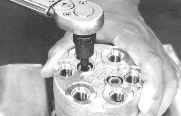
18.Attach socket to universal joint M14 (301). See Figure 3-204.

19.Using a wrench, rotate the socket to tighten universal joint M14 (301) onto casing (101) to tightening torque 34.7±2.1 lb.-ft. (47.1±2.9 Nm).
20.Be sure that all four push-rods (212) are in contact equally.
IMPORTANT:Excessive tightening or wrong positioning of the disc can cause the valve to malfunction.
22.Install adjustment nut M14 (312). See Figure 3-207.
23.Using a spanner wrench, tighten disc (302). See Figure 3-207.

24.Tighten adjustment nut M14 (312) to tightening torque 50.7±3.6 lb.-ft. (68.8±4.9 Nm). See Figure 3-207.

IMPORTANT:Do not allow the position of disc (302) to shift while tightening adjustment nut M14 (312).
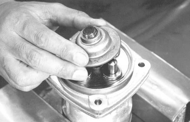
25.Apply grease to the rotating component of universal joint M14 (301) and the end of push-rod (212). See Figure 3-208.
26.Install bellows (501) as shown. See Figure 3209.
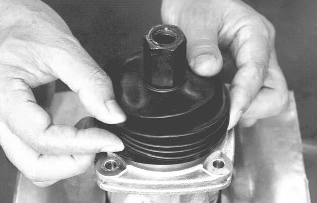
IMPORTANT:Be sure not to damage the bellows.
27.Coat each port with an anti-corrosion spray, according to the manufacturer’s specifications.
28.Insert the blind plugs.