43 minute read
JOHNDEEREENGINE4045TF270(SNAC02633ANDUP)ME12002


SettingtheOpeningPressure
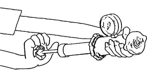
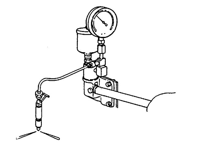
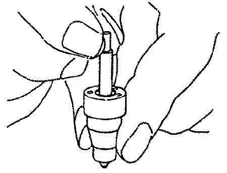
1.Close the pressure gauge valve of the nozzle tester (A). See Figure 4-45.
CorrectingtheOpeningPressure
NOTICE: Only complete these steps if opening pressure measurements are not within the acceptable range of measurements. See “Setting the Opening Pressure.”
4-45 Testing Opening Pressure
2.Rapidly actuate the pump to flush the nozzle.
3.Rapidly actuate the pump to increase the pressure until the nozzle opens. The gauge quickly drops after the nozzle opens.
4.Record the opening pressure measurement.
5.Refer to the following table for acceptable fuel injection nozzle RE48786 opening pressure measurements:
6.If measurements are not acceptable, complete the steps in “Correcting the Opening Pressure.”
Ab Cd
Figure 4-46 Setting Opening Pressure
1.Remove the nozzle from the tester.
2.Insert the nozzle into positioning clip and secure positioning clip into a vice. See Figure 4-43.
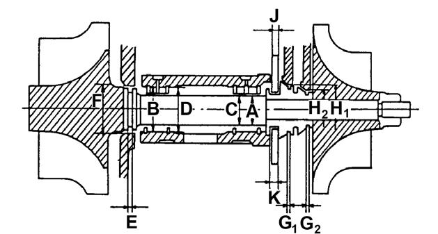
3.Remove lift adjusting lock nut (D). See Figure 4-46.
4.Loosen pressure set screw lock nut (A).
5.Remove the nozzle from the positioning clip and vice.
6.Connect the nozzle to the tester, with the nozzle tip facing downward.
7.Unscrew stroke set screw (B) (two or three rotations) until there is no more contact with stroke set screw (B) when turning pressure set screw (C).
8.Screw pressure set screw (C) clockwise (to the right) to increase opening pressure, or unscrew pressure set screw (C) counter-clockwise (to the left) to decrease opening pressure.
9.Check that the opening pressure is at the high limit of the opening pressure measurement. See step 5, of “Setting the Opening Pressure.”
10.Write down the opening pressure measurement.
11.If measurements are not acceptable, repeat steps 1 through 10 of this procedure.
12.Remove the nozzle from the tester.
13.Insert the nozzle into positioning clip and secure positioning clip in a vice.
14.Tighten pressure set screw lock nut to 7 lb.-ft. (10 Nm). See Figure 4-47.
IMPORTANT:Do NOT use excessive manual force to hold the valve in place because the valve may bend.
4.Check for valve contact by raising the pressure to 200-500 psi (14-34 bar) above the nozzle opening pressure. See “Setting the Opening Pressure” on page222.
NOTICE: It is acceptable for a very small amount of fuel to collect at the nozzle tip, it is not acceptable for a rapid dribble of fuel to flow from the nozzle tip.
5.Remove the nozzle from the nozzle tester.
6.Insert the nozzle into positioning clip and secure the positioning clip into a vice. See Figure 4-49.

AdjustingtheNozzleValveStroke
1.Connect the nozzle to the nozzle tester (A). See Figure 4-48.
2.Actuate the pump to flush fuel through the nozzle. See Figure 4-48.
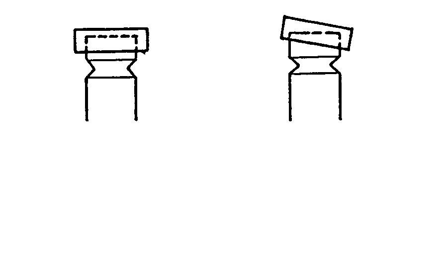
3.Hold the pressure set screw while slowly turning the lift set screw clockwise (to the right) until the valve does not open.
7.Screw lift set screw counter-clockwise (to the left) until there is a tolerance of approximately 1/8 rotation.
8.Hold the pressure set screw while tightening the lock nut of the stroke set screw to 4 lb.-ft. (5 Nm) torque.
9.Complete all steps in “Checking the Opening Pressure” on page218.
10.Close the measuring instrument valve and actuate the nozzle tester to the speed at which the nozzles began to clatter. See “Checking the Clatter” on page219.
11.If the nozzle still clatters, some nozzle valve parts may not be aligned correctly. Screw the pressure set screw repeatedly and reset the valve stroke.
12.Repeat steps 10-11.
13.Clean the nozzle with brass wire brush.
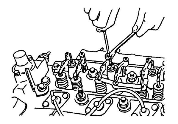
InstallingtheInjectionNozzles
IMPORTANT:Clean the nozzles until they are completely free of oil and grease before installing them.
Nozzle
1.If installed, remove the nozzle hole plug from the cylinder head.
2.Use compressed air to clean the nozzle hole.
NOTICE: Be sure that the cylinder head sealing surface (where the seal washer will be placed) is smooth, free of damage, and free of dirt. A dirty surface may prevent proper sealing. A rough surface may cause the nozzle to become distorted after tightening the attaching screw, causing the valve to stick.
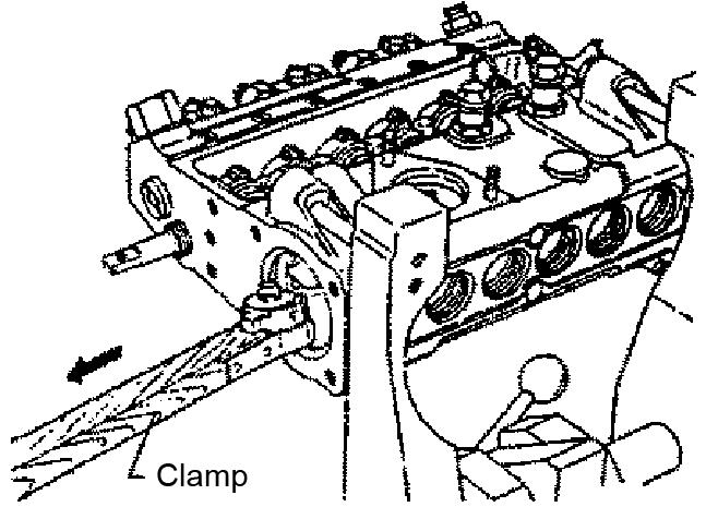
3.Using spacers and clamps, install the nozzle into the nozzle hole while applying a slight twisting motion. See Figure 4-51.
4.Align the nozzle fastening clips and screw the hexagon bolts, but do not fully tighten the hexagon bolts.
5.Loosely connect the fuel pressure line onto the nozzle.
6.Tighten the nozzle fastening clip hexagon bolts to 30 lb.-ft. (40 Nm).
7.Install the fuel return line unit.
8.Tighten the fuel return line unit hexagon nut to 4 lb.-ft. (5 Nm).
9.Bleed air from fuel pressure line. See “Purging Air from the Fuel System: John Deere Engine Model 4045TF270 (SN AC02633 and up)” on page46.
10.Tighten nozzle feed line to 20 lb.-ft. (27 Nm). See Figure 4-52.
5.Insert adapter (A) into fuel injection nozzle hole with nozzle spacer (B) and two nozzle seals (C) as shown. Use holding plate (D) to secure. See Figure 4-53.
6.Screw the fastening screw into the holding plate (D) and tighten it to 27 lb.-ft. (37 Nm).
CheckingCompression
NOTICE: Engine starting speed affects compression pressures. Be sure the battery is fully charged, and thoroughly clean the area around the injection nozzles before checking the compression.
1.Start the engine. If starting a recently used engine, let it run at its rated speed until it reaches its normal operating temperature. If starting a cold engine, allow the engine to run at idle speed for approximately 10-15 minutes to fully warm up all systems.
2.Shut-off the engine. Remove the ignition key and take it with you. Follow the “Mandatory Safety Shutdown Procedure” in the Operator‘s manual.
3.Shut-off the fuel supply.
4.Remove the fuel injection nozzles.
7.Install test gauge (E) onto adapter (A). See Figure 4-54.
8.Reduce the throttle lever to the “STOP” position.
9.Use the starter motor to turn the crankshaft for 10-15 seconds. The minimum acceptable cranking speed: 150 rpm cold/200 rpm hot.
10.Measure the compression pressure in all cylinders and compare the measured values. Compression pressure must be within the following specifications:
•Engine compression pressure must be between 348-406 psi (24-28 bar).
•The maximum acceptable difference between cylinder readings is 51 psi (3.5 bar).
11.If the compression pressure is not within the specifications listed in step 10, complete the steps in “Correcting Low Compression Check Readings” or “Correcting High Compression Check Readings.”
CorrectingLowCompressionCheck Readings
A low compression check reading is a sign of worn or jammed valves.
1.Remove test gauge (E) and adapter (A).
2.Apply oil through the injection nozzle hole and onto the piston ring.
NOTICE: Do not use too much oil and do not apply oil onto the valves.
3.Check the compression pressure. Complete the steps in “Checking Compression” on page225.
4.If necessary, overhaul the cylinder head. See “Removing the Cylinder Head” on page207.
CorrectingHighCompressionCheck Readings
A high compression check reading is a sign of worn or jammed piston rings.
1.Replace the piston rings or install a new piston/ sleeve set.
2.Check the compression pressure. Complete the steps in “Checking Compression” on page225.
3.If necessary, overhaul the cylinders and valves. See “Removing the Cylinder Head” on page207.
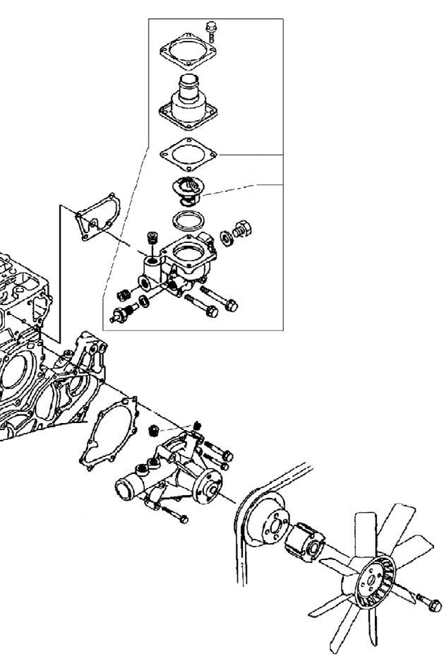
ServicingtheThermostat InspectingtheThermostat
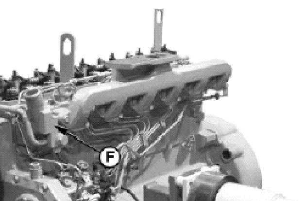
1.Remove the thermostat housing/coolant supplier unit (F). See Figure 4-55.
2.Check the thermostat for corrosion and damage. Replace if necessary.
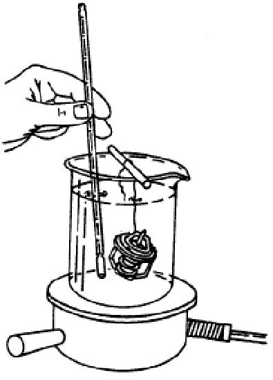
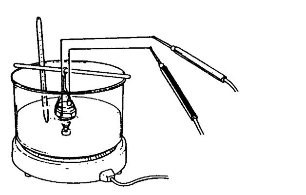
3.Place the thermostat and a thermometer in a container with water. Stir the water as you warm it up. Be careful not to break the thermometer. See Figure 4-56.
4.Check how the thermostat opens and compare the temperatures with the temperatures in the following table.
ServicingtheCoolingSystem
CheckingforWaterLeakage
Caution
Becarefultoavoidburnswhenremovingthe cap.Keepfaceawayfromcap.Covercapwitha cloth,turncapslowlytoreleasepressure.
marked on the radiator cap) of pressure to the cooling system with the pressure pump.
8.Check all cooling system and radiator hose connections and the entire engine for leaks while the pressure is applied.
9.If there are leaks, complete repairs and complete steps 1 through 8. If no leaks are found, but the pressure gauge measures a pressure drop, coolant may be leaking internally in the system or in the area between the cylinder block and cylinder head gasket. Complete repairs and complete steps 1 through 8.
CheckingtheRadiatorCap
HandPump
1.Shut-off the engine. Remove the ignition key and take it with you. Follow the “Mandatory Safety Shutdown Procedure” in the Operator‘s manual.
2.Let the engine cool down and carefully remove the radiator cap.
3.Add coolant to the radiator until it reaches the normal level.
4.Start the engine. If starting a recently used engine, let it run at its rated speed until it reaches its normal operating temperature. If starting a cold engine, allow the engine to run at idle speed for approximately 10-15 minutes to fully warm up all systems.
5.Turn the key fully counter-clockwise to shutoff the engine.
6.Remove the ignition key and take it with you.
IMPORTANT:Do NOT apply excessive pressure to the cooling system, otherwise the radiator and hoses can be damaged.
7.Connect the pressure gauge and adapter to the radiator filler inlet. Apply 14.5 psi (1.0 bar) (as
Figure 4-58 Radiator Cap
RadiatorCap
1.Remove the radiator cap and secure it onto the pressure pump as shown. See Figure 4-58.
2.Using the hand pump, increase the pressure to about 10 psi (0.7 bar). The radiator cap functions correctly if the pressure gauge holds the pressure to about 10 psi (0.7 bar) for 10 seconds.
3.Remove the radiator cap from the pressure gauge, rotate it 180°.
4.Repeat steps 1-2.
5.Radiator cap must open.
Chapter5
YANMARENGINE4TNE106T-NS(SNAB00473-AB03158)
For specifications, see “John Deere 4045TF270 and Yanmar 4TNE106T-NS Specifications” on page9.
YanmarEngineModel4TNE106T-NSOverview
ME12002YANMARENGINE4TNE106T-NS(SNAB00473-AB03158)
Coolingwaterpump Alternator
Intakemanifold
Exhaustmanifold
Startingmotor
ServicingtheComponents
CheckingValveTipClearance CAUTION
Beforecompletingthesesteps,disconnectthe batterycableconnectedtothenegativeterminaltopreventtheenginefromaccidentally startingwhilecheckingthevalvetipclearance.
Cylinderheadcover
Cover Seal
3.Remove the cylinder head gasket and valve cover seal. See Figure 5-7.
4.Manually turn the crankshaft to bring the piston of the No. 1 cylinder (firing order: 1-3-4-2) to its compression top dead center position while watching the rocker arm motion, timing scale and the crankshaft pulley top mark position. At the top mark position, both the intake and exhaust valves are closed.
1.Shut down the engine. Follow the mandatory safety shutdown procedure in the Operator's manual.
NOTICE: Only check the valve clearance after the engine is cold.
2.Remove the cylinder head cover. See Figure 56.
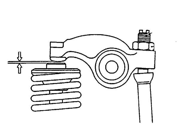
5.Insert a 0.2 or 0.3 mm thickness gauge between the rocker arm and valve cap and record the valve clearance (A). See Figure 5-8.
6.Remove the thickness gauge.
7.Loosen lock nut (C) and adjustment screw (B).
8.Check the valve cap for any inclination, dirt and wear. See Figure 5-9.
11.Install the valve cover seal, cylinder head gasket and cylinder head cover. See Figure 5-12 and Figure 5-13.
9.If necessary, insert a 0.2 or 0.3 mm thickness gauge between the rocker arm and valve cap. See Figure 5-10.
10.Adjust the valve clearance to 0.25 ~ 0.35 mm and tighten the lock nut to ~ 11 lb.-ft. (~ 15 Nm). See Figure 5-11.
MeasuringCompressionPressure
InspectingtheThermostat
Measuring Pressure
1.Start the engine. Follow the Engine Start Procedure in the Operator‘s manual.
2.After warming up the engine, remove the fuel injection pipes and valves from the cylinder.
3.Crank the engine with the regulator handle at the stop position (no injection state) before installing the compression gauge adapter.
4.Install the compression gauge and adapter at the cylinder.
5.With the engine set to no injection state, use the starter motor to crank the engine until the compression gauge reading stabilizes.
6.Be sure the compression gauge reading stabilizes at compression pressure 508 psi (35 bar), 250 rpm. See “John Deere 4045TF270 and Yanmar 4TNE106T-NS Specifications” on page9.
1.Disassemble the thermostat. See Figure 5-15 and Figure 5-16.
Thermometer
CheckingforCoolingSystemWater Leakage
5-17 Thermostat Inspection
2.Heat the thermostat in a container filled with water. See Figure 5-17.
3.Check if thermostat opens at the temperature specified on the thermostat. Check by using a thermometer.
InspectingtheThermoswitch
5-19 Hand Pump
CheckingforLeakage
1.Add coolant to the radiator until it is completely full.
2.Attach a hand pump onto the radiator as shown. See Figure 5-19.
3.Operate the hand pump as shown and increase the pressure in the cooling system to about 15 psi (1 bar).
4.Check the lines and connections for leaks if the pressure measurement on the pressure gauge drops.
CheckingtheRadiatorCap
5-18 Thermoswitch Inspection
1.Place the thermoswitch in a container filled with antifreeze. See Figure 5-18.
2.Heat the antifreeze while measuring the fluid temperature. The switch is normal if the voltameter shows continuity when the fluid temperature reaches 225°-235°F (107°-113°C).
5-20 Radiator Cap
1.Remove the radiator cap and mount it onto the adapter as shown. See Figure 5-20.
2.Operate the hand pump as shown and increase the pressure to about 15 psi (1 bar) (stamped onto the radiator cap).
3.Check that the radiator cap opens. If the radiator cap does not open, replace the radiator cap.
CheckingtheV-beltTension
1.Shut-off the engine. Remove the ignition key and take it with you. Follow the “Mandatory Safety Shutdown Procedure” in the Operator‘s manual.
2.Open the engine cover.
InspectingtheFuelInjectionValveand SprayPattern
Warning
Wearprotectiveglasseswhentestinginjection fromthefuelinjectionvalve.Nevermanually handletheinjectionnozzlebecausetheoiljettingoutfromthenozzleissetathighpressure. Contactmaycauselossofsightorinjury.
MeasuringFuelInjectionPressure
Check
3.Push the center of the V-belt between the alternator and cooling water pump with a finger. The tension is normal if the deflection is 0.40.6” (10 - 15 mm). See Figure 5-21.
NOTICE: If the V-belt is new, tension is normal if the deflection is 0.3 - 0.4” (7 - 9 mm).
Figure 5-23 Fuel Injection Valve
If necessary, during these steps refer to Figure 5-24 on page239 to view the fuel injection valve structure.
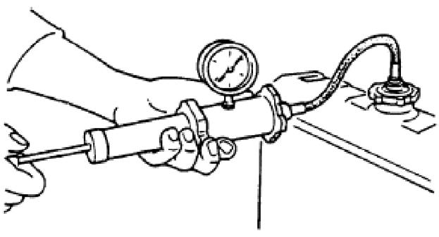
1.Connect fuel injection valve (B) to high pressure pipe of nozzle tester (A). See Figure 5-23.
2.Operate the nozzle tester lever slowly and read the pressure when fuel injection from the fuel injection valve (B) begins.
3.If the measured injection pressure is below 3191-3336 psi (220-230 bar), replace the pressure adjusting shim with a thicker one. If the measured injection pressure is above 3191-3336 psi (220-230 bar), replace the pressure adjusting shim with a thinner one. Approximately: 0.1 mm = 276 psi (19 bar).
4.If not, adjust the V-belt tension by inserting a bar as shown and adjusting the alternator. See Figure 5-22.
5.Close the engine cover.
4.Check the fuel injection valve (B) for drips after it has ejected fuel.
5.Operate the nozzle tester lever and create a pressure of about 290 psi (20 bar) below injection pressure. Check if fuel escapes from the fuel injection valve (B).
CheckingtheNozzleJet(spraypattern)
After adjusting the specified valve opening pressure, check the spray pattern and seat-oil tightness using a nozzle tester.
Uppernozzlescrewfitting
Spacers
Compressionspring
Compressionspringseat
Pressurespringcentering
Nozzleneedle
Nozzlebody
Lowernozzlescrewfitting
1.Remove injection lines and injection nozzles.
2.Connect injection nozzle to the high pressure line of the nozzle tester.
3.Quickly create pressure until the nozzle ejects fuel (ejection 3-4 times).
4.Hold a white sheet of paper about 12” (30 cm) away from the nozzle while the nozzle ejects fuel.
NOTICE: New nozzles are coated with rustpreventive oil and are pasted with seal peel to shut-off outer air.
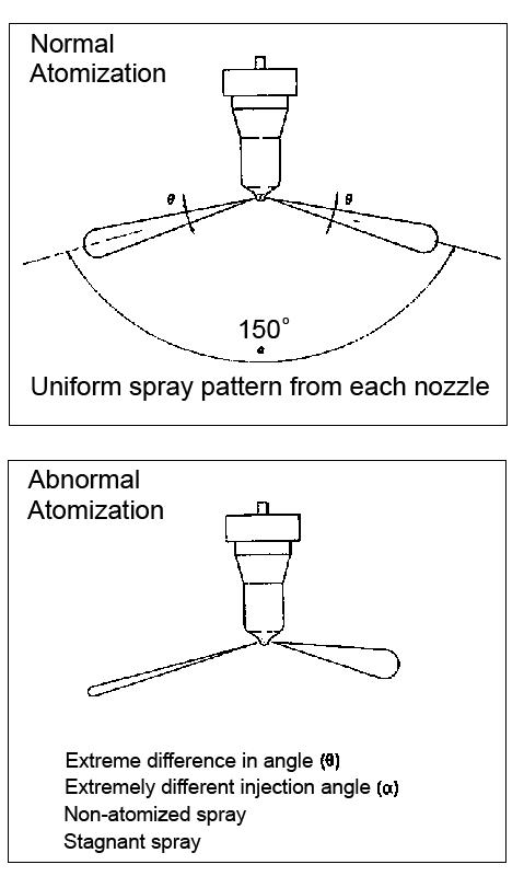
5.The nozzle jet must create an “optimal” shape on the paper as shown. See Figure 5-26.

6.Replace the fuel injection valve if abnormal atomization occurs. See Figure 5-25.
NozzleValveSlideTest
InjectionTimingCheck
1.Wash the nozzle valve in clean fuel oil.
2.Vertically position the nozzle body as shown. See Figure 5-27.
3.Insert the nozzle into the body to about 1/3 of its length as shown.
The nozzle valve is normal if it smoothly falls by its own weight into the nozzle body.
If nozzle is new, before using nozzle, remove the seal peel, and immerse it in clean diesel oil or an equivalent solvent to clean the inner and outer surfaces and to remove rust-preventive oil.
1.Check that the fuel system is bled. If necessary, complete the steps in “Purging Air from the Fuel System: John Deere Engine Model 4045TF270 (SN AC02633 and up)” on page46.
2.Check that the matching mark made on the fuel injection pump is aligned to the matching mark made on the control unit.
Figure 5-30 Ignition Key Switch (SN AB01968 and up)
3.Turn the ignition key to the “I” position on models SN AB01968 and up. See Figure 5-30.
Turn the ignition key to the RUN position, one position “clockwise” (to the right) from the OFF position, on models SN AB01967 and before.
4.Remove the injection line from the No. 1 cylinder. The No. 1 cylinder is the cylinder furthest from the radiator.
5.Rotate the crankshaft in the direction of rotation: “clockwise” (to the right). Stop turning when the No. 1 cylinder on the fuel injection pump opens and fuel flows from the opening.
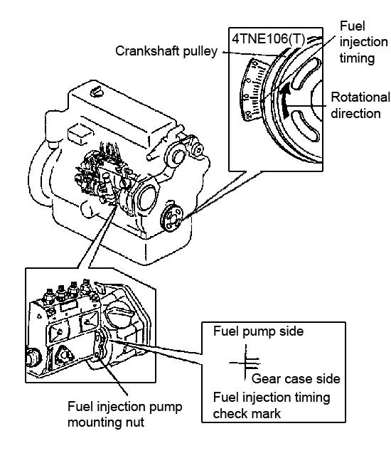
6.Check the injection time mark on the Vgrooved pulley. The No. 1 cylinder is positioned near top dead center if this mark is made near the 0° mark. See Figure 5-29.
7.Clean the opening of the fuel injection pump.
8.Rotate the crankshaft approximately 20° against the direction of rotation: “counterclockwise” (to the left).
9.Rotate the crankshaft very slowly in the direction of rotation until the fuel at the opening of the fuel injection pump nearly overflows.
10.Check the injection time using the mark on the timing scale. The injection time value must be 11-13° before the 0° position. See Figure 5-29.
If the injection time value is not 11-13° before the 0° position, complete the steps in “Correcting the Ignition Timing” on page241.
11.Repeat steps 6 through 10 three times.
12.Re-install the injection line.
13.Check the No. 3, No. 4, and No. 2 cylinders, in that order. Repeat steps 1-12 for each cylinder.
NOTICE: Turn the crankshaft 180° each time prior to checking the No. 3, No. 4, and No. 2 cylinders.
CorrectingtheIgnitionTiming
NOTICE: Only complete these steps if the injection time value is not within 11-13° before the 0° position.
1.Loosen the fuel injection pump fastening screws.
2.Rotate the fuel injection pump toward or away from the engine. Rotating toward the engine sets an earlier injection time, rotating away from the engine sets a later injection time. Each line on the check mark = a degree for the injection time.
3.Tighten the fuel injection pump fastening screws.
4.Check the injection time value again. Repeat steps 6-10 of “Injection Timing Check” on page240.
CheckingtheOilPressureSwitch
1.Remove the cable connection from the oil pressure switch (in the cutoff solenoid area).
2.Start the engine.
3.Check the engine for correct idling speed.
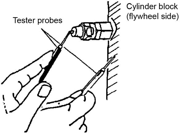
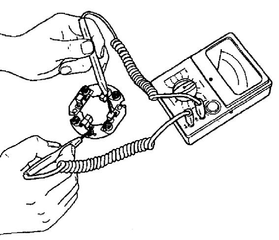
4.Using an ohmmeter, measure oil pressure switch resistance. See Figure 5-31.
5.Determine if the oil pressure switch is acceptable or defective. Refer to the following table:
Oil pressure switch acceptable Infinite resistance
Oil pressure switch defective If any oil can pass
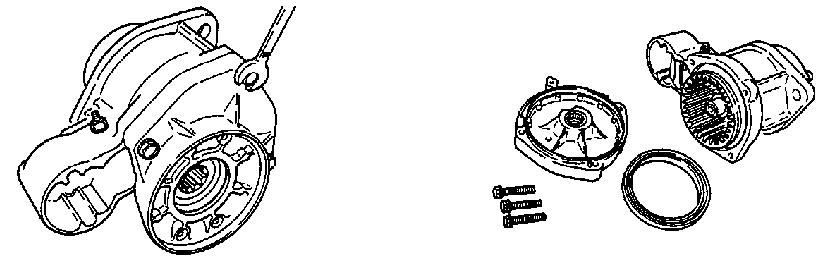
ServicingtheWaterPump
DisassemblingtheWaterPump
1.Remove the alternator.
2.Remove the fan, V-belt, and pulley (2). See Figure 5-33.
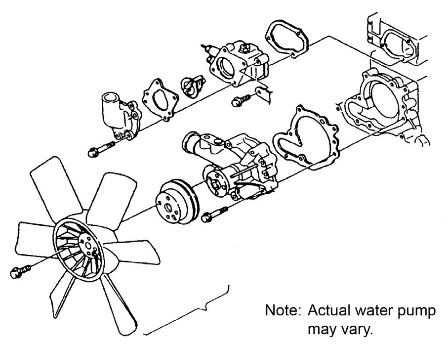
3.Remove the thermostat cover (3).
4.Remove the water pump (4).
5.Remove the thermostat (5).
ServicingtheWaterPump
1.Check the water pump bearing for abnormal noise, sticking or play, and bearing water leakage.
2.If replacement is necessary, replace the entire water pump assembly.
3.Inspect the thermostat function. See “Inspecting the Thermostat” on page236.
AssemblingtheWaterPump
1.Install the thermostat (5).
2.Install the water pump (4).
3.Install the thermostat cover (3).
4.Install the fan, V-belt, and pulley (2).
5.Install the alternator.
AdjustingtheRadiatorFan
Adjust the air guide plate/air fan according to the following specifications:
Fan exhaust: 1/3 of the fan width inside the air guiding box.
Fan intake: 2/3 of the fan width inside the air guiding box.
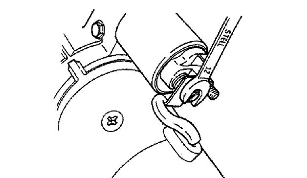
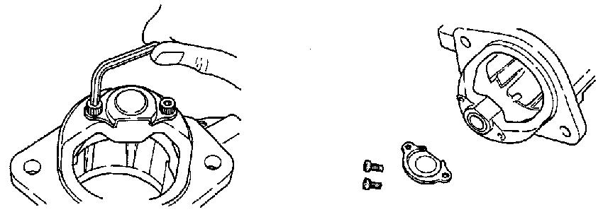
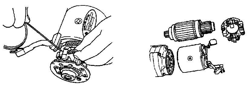
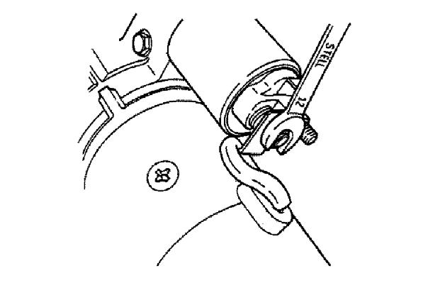
1.Using a 12 mm spanner wrench, loosen magnetic switch nut M8 as shown and disconnect the lead (1). See Figure 5-36 and Figure 5-37.
2.Using a 10 mm spanner wrench, remove bolts M6 and magnetic switch (2). See Figure 5-36 and Figure 5-38.

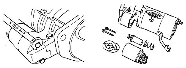
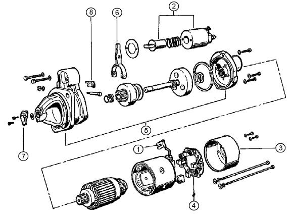
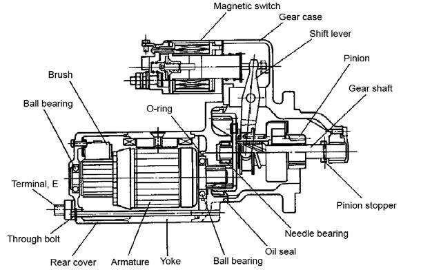
3.Using a 8 mm spanner wrench, remove brush holder tightening screws and bolts M5. See Figure 5-39.
4.Remove rear cover (3) from the yoke using a standard-head screwdriver.
5.For the negative (-) brush, move the brush spring into contact with the brush side and lift the commutator surface. See Figure 5-40.
6.For the negative (+) brush, remove the brush from the brush holder (4). See Figure 5-36 and Figure 5-40.
7.Disassemble the yoke and armature.
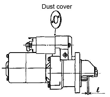
12.Remove the dust cover, shift lever, gear case, and gear shaft.
13.Using a 4 mm hexagon wrench, remove bolts M5 and remove the dust cover from the gear case. See Figure 5-44.
14.Remove the gear case dust cover (7). See Figure 5-43 and Figure 5-44.
8.Using a 10 mm spanner wrench, remove three bolts M6 from the gear case. See Figure 5-41.
9.Remove the oil seal
10.Disassemble the gear case and center bracket (5). See Figure 5-36 and Figure 5-41.
15.Slide the pinion stopper toward the pinion. See Figure 5-45.
16.Using a standard-head screwdriver, remove the pinion stopper clip.
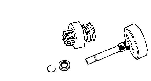
17.Remove the pinion (8). See Figure 5-43 and Figure 5-45.
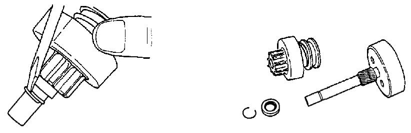
11.Using a 10 mm spanner wrench, remove nut M6 and the shift lever pin (6). See Figure 5-36 and Figure 5-42.
InspectingandMaintainingtheArmature
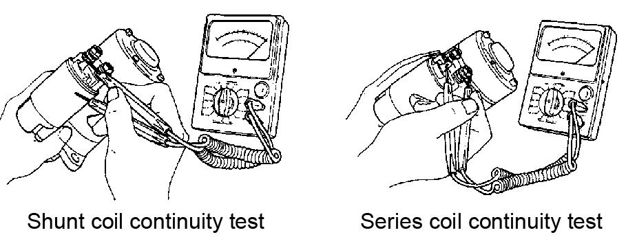
4.Complete the following armature coil continuity and ground tests. See Figure 5-48.

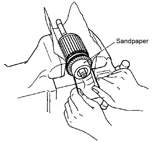
1.Place the armature into a vice as shown. See Figure 5-46.
2.Inspect the commutator surface. If the surface is rough, sand the armature using sandpaper as shown.
5.Replace as necessary according to test results.
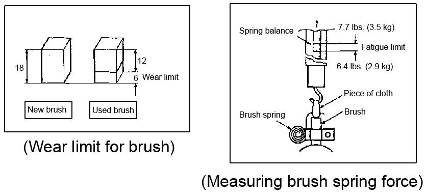
3.Measure the depth of the insulating material between commutator segments as shown. If the depth is less than 0.2 mm, repair using a lathe. See Figure 5-47.

6.Complete the following field coil continuity and ground tests. See Figure 5-49.

7.Check the brush and brush spring force wear. See Figure 5-50.
8.Check the brush movement, if the brush does not move smoothly, inspect the brush holder for bending, binding, dirt, etc. Clean or replace as necessary.
9.Check the continuity between the insulated brush holder (+) and the brush holder base (-). The brush holder is grounded, if there is electrical continuity, replace the brush holder. See Figure 5-51.

10.Complete the following magnetic switch continuity tests. See Figure 5-52 and Figure 5-53.

11.Replace as necessary according to test results.
12.Check pinion teeth for wear and/or damage. Replace as necessary.
13.Check that the pinion slides smoothly. Repair or replace pinion if it is damaged, rusted, or fails to slide smoothly.
14.Check springs for damage. Replace as necessary.
15.Check the ball bearing for abnormalities and/or abnormal noises. Replace as necessary.
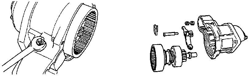
AssemblingtheStarter
1.While assembling the starter, apply NPCFC6A grease to sliding portions and head of plunger, pinion metal and gear case metal portions, pinion spline portions, shift lever sliding portions.
2.While assembling the starter, apply MAPTEMP SRL grease to the deceleration gear.
3.Install the pinion (8). See Figure 5-55 and Figure 5-56.
4.Install the pinion stopper clip.
5.Slide the pinion stopper toward the pinion. See Figure 5-56.
10.Using a 10 mm spanner wrench, install nut M6 and the shift lever pin (6). See Figure 5-58 and Figure 5-59.
6.Install the gear case dust cover (7). See Figure 5-55 and Figure 5-57.
7.Using a 4 mm hexagon wrench, install bolts M5 and install the dust cover onto the gear case. See Figure 5-57.
8.Install the dust cover, shift lever, gear case, and gear shaft. Check and replace any worn or damaged gear shaft washers.
9.Check that the gear shaft thrust is between 0.05-0.3 mm. If thrust is greater than 0.3 mm, add a thrust washer so that the thrust is between 0.05-0.3 mm.
11.Assemble the gear case and center bracket (5). See Figure 5-59 and Figure 5-60.
12.Install the oil seal.
13.Using a 10 mm spanner wrench, install three bolts M6 onto the gear case. See Figure 5-60.
14.Assemble the yoke and armature.
15.For the negative (+) brush, install the brush onto the brush holder (4). See Figure 5-59 and Figure 5-61.
16.For the negative (-) brush, remove the brush spring from contact with the brush side and install onto the commutator surface. See Figure 5-61.
21.Using a 12 mm spanner wrench, install magnetic switch nut M8 as shown. See Figure 564.
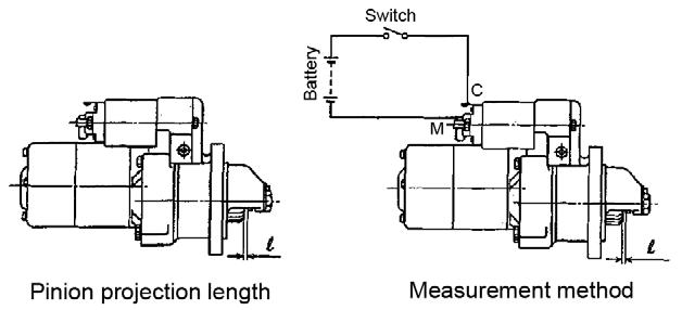
MeasuringthePinionProjectionLength
17.Install the rear cover (3) onto the yoke.
18.Using a 8 mm spanner wrench, install brush holder tightening screws and bolts M5. See Figure 5-62.
1.When the pinion is protruded by the magnetic switch, measure the pinion moving distance in the thrust direction. The moving distance should be between 0.3-1.5 mm. See Figure 565.
19.Using a 10 mm spanner wrench, install bolts M6 and install magnetic switch (2). See Figure 5-59 and Figure 5-63.
2.If the moving distance is not between 0.3-1.5 mm, adjust the dust cover. See Figure 5-66.
20.Connect the lead (1). See Figure 5-59.
1.Disconnect the cable from the negative battery terminal.
2.Remove electrical connections (2) from the alternator. See Figure 5-68.
3.Loosen the screws and remove the V-belt (3, 4). See Figure 5-68.
4.Remove the screws and alternator (3, 4). See Figure 5-68.
5.Check the V-belt tension. See “Checking the V-belt Tension” on page238.
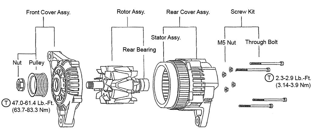
DisassemblingtheAlternator
Figure 5-69 M5 Through Bolt
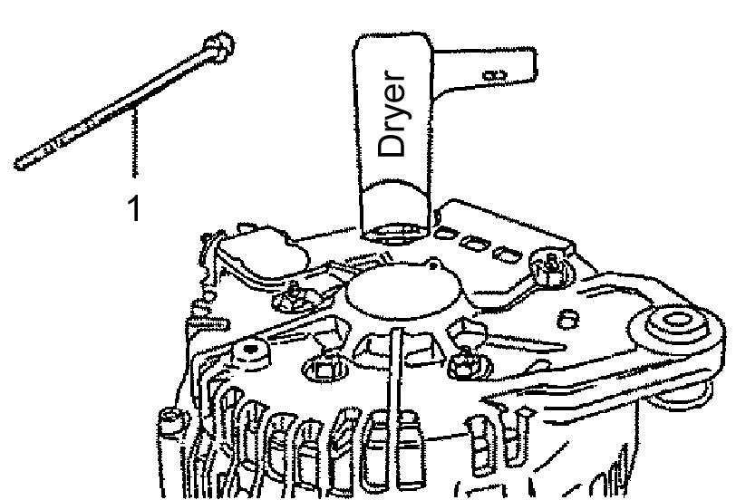
1.Remove M5 through bolt (1) as shown. See Figure 5-69.
2.Using a dryer, blow hot air onto the rear cover for approximately one minute or until the rear cover temperature rises approximately 122°F (50°C).
3.Insert two standard-head screwdriver tip into the gap between the front cover and stator core, at two separate places, to separate the front cover and rotor (front side) from the rear cover and stator (rear side).
IMPORTANT:Do not damage the stator core with the screwdriver.
4.Remove pulley nut assembly (2), pulley (3), and rotor (4). See Figure 5-70.
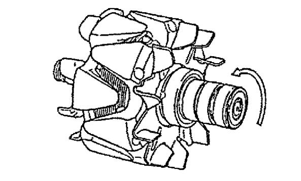

5.Secure the rotor into a vice.
6.Using a 24 mm spanner wrench, remove pulley nut M16.
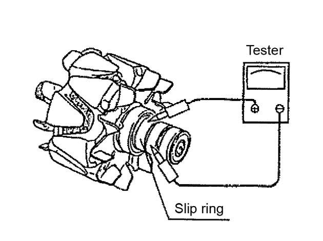
3.Using a circuit tester as shown, check the continuity between slip rings. If there is a disconnection in the rotor coil, replace the rotor. See Figure 5-72.
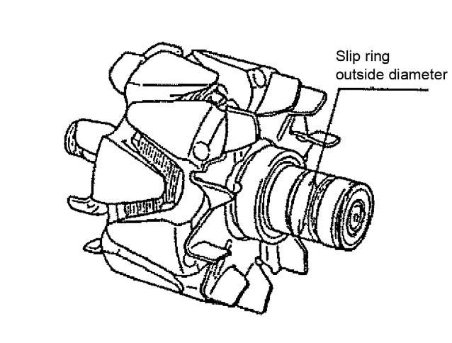
1.Measure the outside diameter of the slip ring. If the slip ring is worn by 1.0 mm or more from the standard 27.0 mm outside diameter, replace the slip ring. See Figure 5-71.
2.Inspect the slip ring surface for smoothness and be sure there is no oil adhesion. If the slip ring surface is too rough, apply a “fine” sandpaper to the surface. If the slip ring surface is stained, clean the surface using alcohol and a cloth.
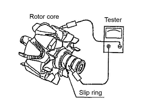
4.Using a circuit tester as shown, check the continuity between the slip ring and rotor core and shaft. If there is a rotor coil short circuit, replace the rotor. See Figure 5-73.
5.Inspect the rear side ball bearing. If abnormal rotation or sound exists, replace the ball bearing. See Figure 5-74.
AssemblingtheAlternator
1.Using a 24 mm spanner wrench, install pulley nut M16. See Figure 5-75.
2.Install pulley nut assembly (2), pulley (3), and rotor (4).
3.Secure the front cover and rotor (front side) onto the rear cover and stator (rear side).
5.Insert a pin and force the brush into the brush holder as shown. See Figure 5-77.
4.Install M5 through bolt (1). See Figure 5-76.
6.Using a dryer, blow hot air onto the rear cover for approximately one minute or until the rear cover temperature rises approximately 122°F (50°C). See Figure 5-78.

7.Extract the pin inserted in step 5. See Figure 579.
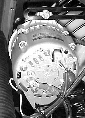
InstallingtheAlternator
Figure 5-80 Alternator
1.Install screws and V-belt (3, 4). See Figure 580.
2.Install screws and alternator (3, 4). See Figure 5-80.
3.Install electrical connections (2) onto the alternator. See Figure 5-80.
4.Re-connect the negative battery cable.
Figure 5-81 Fuel Feed Pump
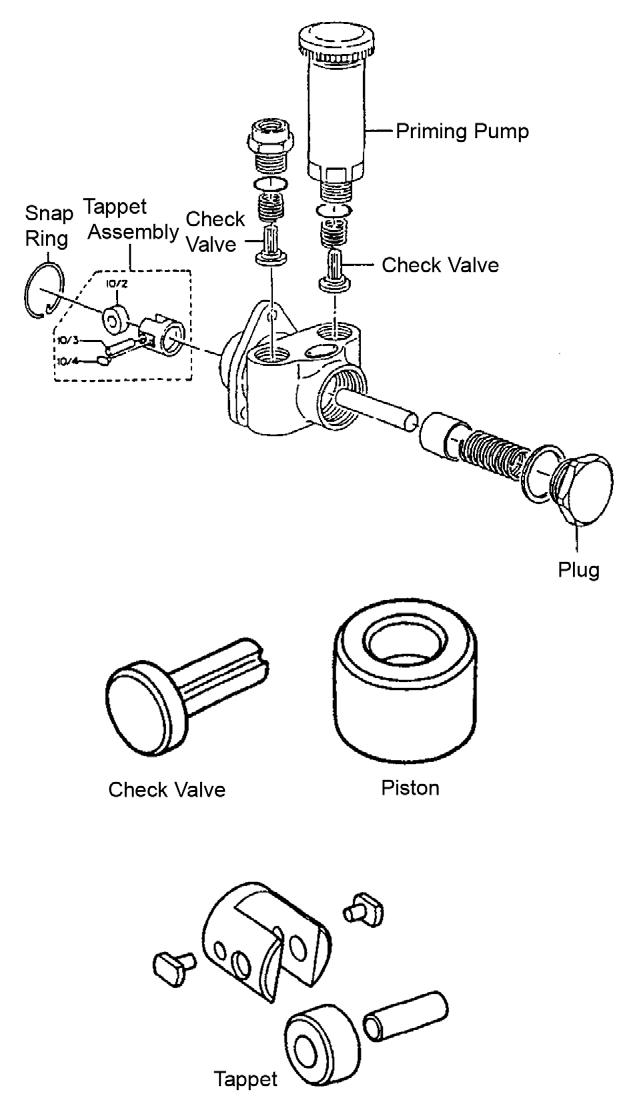
1.Remove the feed pump assembly from the fuel injection pump.
2.Remove the priming pump and check valve. See Figure 5-81.
3.Remove the plug and check valve from the fuel outlet side.
4.Remove the plug.
5.Remove the piston.
6.Remove the snap ring.
7.Remove the tappet assembly, spring and push rod.
InspectingFuelFeedPumpParts
CheckValve
1.Check for damage and wear.
2.Replace the check valve if there is any damage or wear.
Piston
1.Check for surface defect and wear.
Springs(PistonandCheckValve)
1.Check for surface defect, fatigue.
2.Check valve piston and rust.
Tappet
1.Check for surface defect and wear.
2.Replace the tappet if the push rod outer surface is worn.
1.Install the tappet assembly, spring and push rod. See Figure 5-81.
2.Install the snap ring.
3.Install the piston.
4.Install the plug.
5.Install the plug and check valve onto the fuel outlet side.
6.Install the priming pump and check valve.
7.Install the feed pump assembly onto the fuel injection pump.
ServicingtheFuelInjectionPump
RemovingtheFuelInjectionPump
1.Remove the fan (1), pulley and V-belt (1) from the engine body. See Figure 5-83.
2.Remove the fuel injection pipe (2), fuel oil piping, fuel return pipe and rear stay.
3.Remove the fuel injection pump drive gear.
4.Remove the fuel injection pump (8).
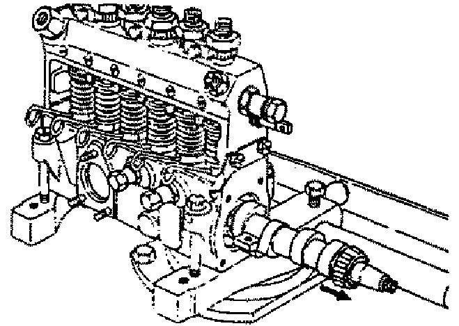
DisassemblingtheFuelInjectionPump
11.Remove the plunger and barrel.
12.Remove the control rack from the pump housing.
ServicingtheFuelInjectionPump
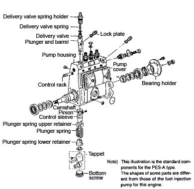
Figure 5-84 Fuel Injection Pump
NOTICE: Group all parts for re-assembly. Replace any defective parts.
1.Remove the fuel feed pump. See “Disassembling the Fuel Feed Pump” on page254.
2.Remove the governor cover. See “Disassembling the Governor Cover” on page260.
3.Remove the governor housing. See “Disassembling the Governor Housing” on page260.
4.Using a socket wrench handle, remove the bottom screw.
5.Remove the fuel injection pump cover. See “Removing the Fuel Injection Pump” on page256.
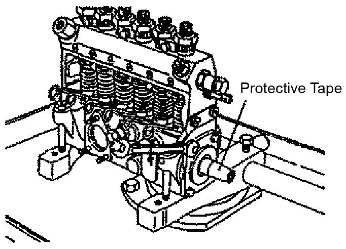
6.Move the tappet away from the camshaft. See “Disassembling the Tappet and Camshaft” on page261.
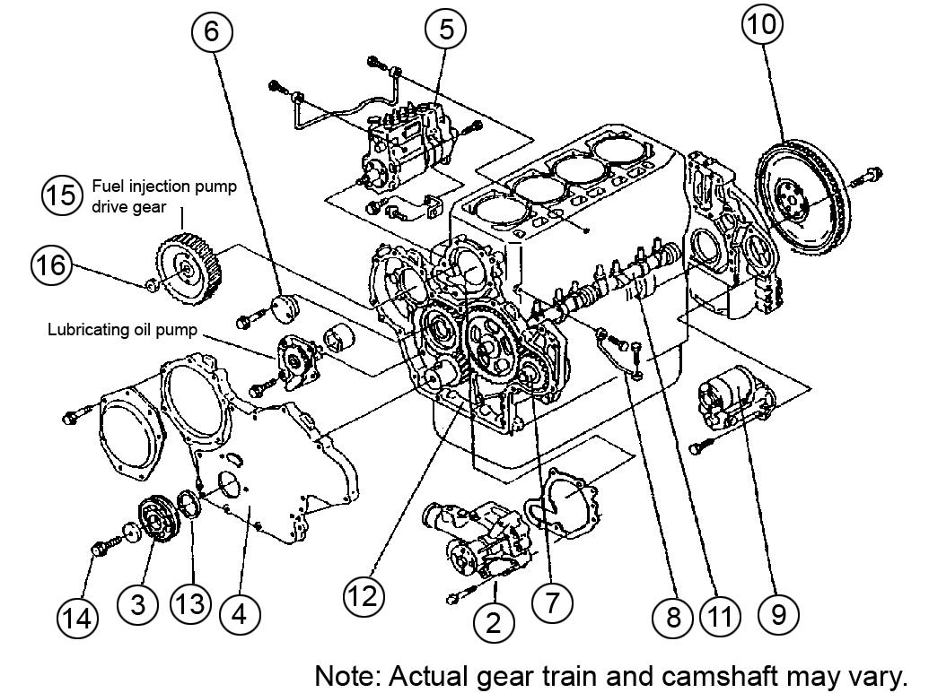
7.Remove the bearing holder, camshaft, and tappet. See “Disassembling the Tappet and Camshaft” on page261.
8.Remove the plunger spring, plunger spring lower retainer, and plunger spring upper retainer. See Figure 5-84.
9.Remove the control sleeve and pinion.
10.Remove the lock plate, delivery valve, delivery valve spring, and delivery valve spring holder.
Figure 5-85 Fuel Pump Driving Gear
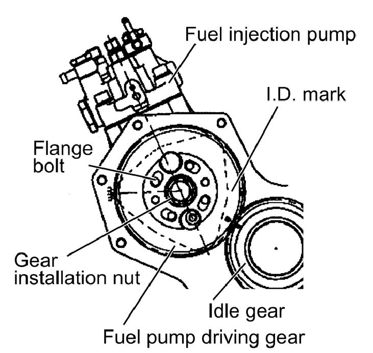
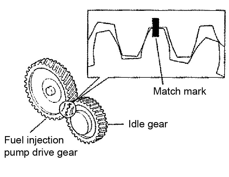
1.Make matching marks on the pump drive gear gearing part and the idle gear. See Figure 5-85.
2.Remove the gear installation nut. See Figure 585.
3.Remove fuel pump drive gear nut (5). See Figure 5-83 on page256.
NOTICE: When removing the drive gear nut, do not drop it into the inside of the gear case.
4.Remove fuel injection pump drive gear (4) from the fuel pump using a gear puller. See Figure 5-83 on page256.
5.Make a mark on the fuel injection pump and use a sticker to record the fuel injection pump installation angle.
6.Remove the fuel injection pump (8). See Figure 5-83 on page256.
InspectingFuelInjectionPumpParts
1.Wash all parts before inspection.
2.Inspect parts for excessive wear.
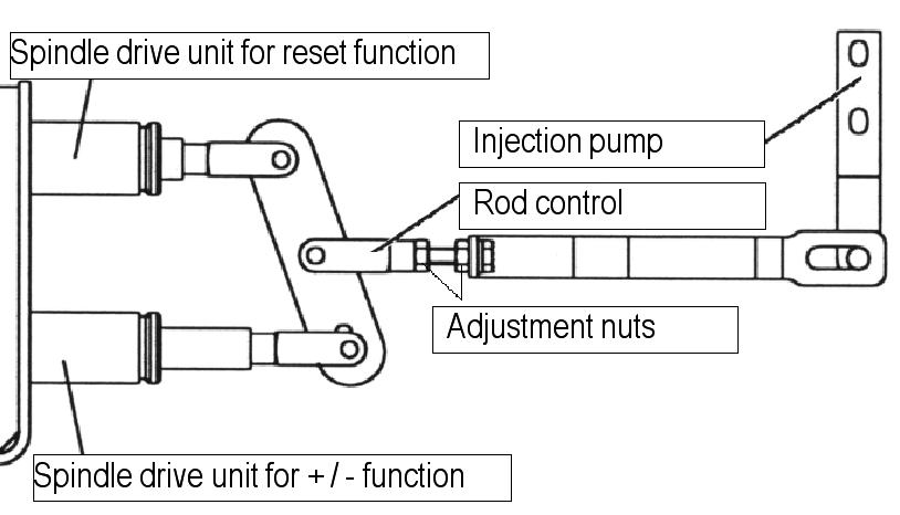
AdjustingtheSpindleDriveUnitRod Control
IMPORTANT:Be sure to set the proper clearance. If the clearance is too small, the injection-pump rod can be damaged. If the clearance is too large, the engine maximum speed will be low.
ServicingtheFuelInjectionPump Gears
1.Adjust the rod control nut to adjust the spindle motor minimum and maximum movement. See Figure 5-86 and Figure 5-87.

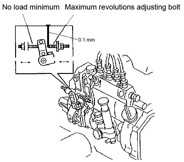
2.Insert a thickness gauge (0.1 mm) between the minimum and maximum adjusting bolts of the injection pump to adjust the rod control in the minimum and maximum position of the spindle motor. See Figure 5-88.
Figure
Gears DisassemblingtheGears
1.Make a matching mark on the pump drive gear and idle gear. See Figure 5-89.
2.Remove the fuel injection pump drive gear.
ReassemblingtheGears
1.Assemble the pump drive gear and idle gears by aligning the match marks.
2.Tighten each gear nut to tightening torque 61.4-68.7 lb.-ft. (83.3-93.1 Nm).
AssemblingtheFuelInjectionPump
InstallingtheFuelInjectionPump
NOTICE: Group all parts for re-assembly. Replace any defective parts.
1.Install the control rack onto the pump housing. See Figure 5-84.
2.Install the plunger and barrel.
3.Install the lock plate, delivery valve, delivery valve spring, and delivery valve spring holder.
4.Install the control sleeve and pinion.
5.Install the plunger spring, plunger spring lower retainer, and plunger spring upper retainer.
6.Install the bearing holder, camshaft, and tappet. See “Assembling the Tappet and Camshaft” on page264.
7.Install the fuel injection pump cover. See “Installing the Fuel Injection Pump” on page259.
8.Using a socket wrench handle, install the bottom screw.
9.Install the governor housing. See “Assembling the Governor Housing” on page260.
10.Install the governor cover. See “Assembling the Governor Cover” on page260.
11.Install the fuel feed pump. See “Assembling the Fuel Feed Pump” on page255.
Figure 5-91 Fuel Injection Pump
1.Install the fuel injection pump (8). See Figure 5-91.
For a larger view of Figure 5-91, see Figure 583 on page256.
2.Install the fuel injection pump according to the mark made and sticker applied while completing step 5 in “Removing the Fuel Injection Pump” on page256.
3.Install fuel injection pump drive gear (4) onto the fuel pump.
4.Install fuel pump drive gear nut (5).
5.Install and tighten the gear installation nut to tightening torque 113~123 Nm (83~91 lb.-ft.).
6.Install the fuel injection pump drive gear cover.
7.Install fuel injection pipe (2), fuel oil piping, fuel return pipe and rear stay.
8.Install cooling fan (1), pulley and V-belt (1) onto the engine body.
ServicingtheGovernor
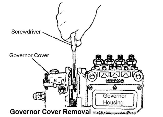
DisassemblingtheGovernorCover
DisassemblingtheGovernorHousing
Governor Housing
Extractor
Figure 5-93 Flyweight Removal
Figure 5-92 Governor Cover
1.Disconnect the link connection by pushing the link leaf spring down with a screwdriver and shifting the governor cover to the left (or right). The link is connected to the control rack and the starting spring is connected to the spring eye.
2.Using a long-nosed pliers, remove the starting spring from the spring eye.
3.Remove the governor cover from the governor housing.
NOTICE: When removing the governor cover from the governor housing, do not bend the governor cover to the left (or right). If the governor cover is bent while the link is connected, a bent link increases the sliding resistance of the control rack after reassembling the governor, causing stiff governor movement.
AssemblingtheGovernorCover
1.Apply a coat of sealant onto the connecting sides of the governor cover and governor housing.
2.Install the governor cover onto the governor housing.
3.Using a long-nosed pliers, install the starting spring into the spring eye.
4.Connect the link connection by installing the link leaf spring.
1.Using a wrench, remove the camshaft nut and spring washer from the camshaft.
2.Remove the flyweight from the camshaft.
3.Screw the extractor into the flyweight holder threaded portion as shown. See Figure 5-93.
4.Remove the flyweight assembly.
5.Remove the governor housing from the injection pump housing.
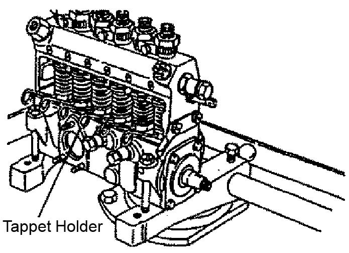
6.Disconnect the camshaft and tappet by inserting the tappet holder between the tappet adjusting bolt and nut in the pump housing.
7.Remove and retain seven bolts from the governor housing.
8.Using a wooden or plastic hammer, tap the governor housing to remove it.
AssemblingtheGovernorHousing
1.Install the governor housing by tapping it with a wooden or plastic hammer.
2.Secure the governor housing by installing the seven bolts.
3.Connect the camshaft and tappet by removing the tappet holder from the tappet adjusting bolt and nut in the pump housing.
4.Apply Yanmar sealant No. 977770-01212 or equivalent onto the facing sides of the governor housing and injection pump housing.
5.Install the governor housing onto the injection pump housing.
6.Install the flyweight assembly onto the camshaft and tighten the mounting nut tightening torque to 39.8-47.0 lb.-ft. (53.9-63.7 Nm).
7.Using a wrench, install the camshaft nut and spring washer onto the camshaft.
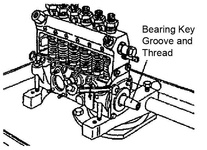
4.Wrap oil seal protecting tape around the bearing key groove and thread. See Figure 5-95.
5.Using a wooden or plastic hammer, tap the camshaft on the opposite side.
6.Insert a screwdriver into the gap and pry for removal.
ServicingtheTappetand Camshaft
DisassemblingtheTappetand Camshaft
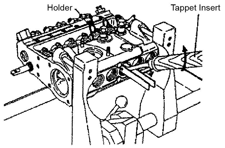
1.Using a socket wrench handle, remove the bottom screw.
2.Position the camshaft at top dead center and insert the special service tool (tappet holder) into the tappet hole.
7.Position the drive side camshaft at top dead center. See Figure 5-96.
8.Remove the camshaft by pulling it toward the drive side.
9.Position the tappet insert underneath the tappet holder as shown. See Figure 5-97.
10.Remove the tappet holder by using the tappet insert to elevate the tappet roller.
11.Remove the tappet from the clamp camshaft hole. See Figure 5-98.
InspectingtheTappetandCamshaft Parts
InspectingthePumpHousing
Check for threaded hole cracks, wear and damage.
InspectingthePlungerandDelivery Springs
Check for surface defects, cracks, uneven wear, corrosion and rust.
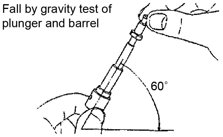
3.Remove and release the plunger. See Figure 599.
The plunger condition is normal if the plunger slides down smoothly because of its own weight.
4.Repeat step 3 several times while turning the plunger to different angles.
InspectingtheDeliveryValve
InspectingthePlungerandBarrel
1.Check the barrel at the lead portion for surface defect, uneven corrosion, and wear.
2.After washing, tilt the barrel approximately 60°.
1.Check the delivery valve at the piston for surface defect, corrosion and wear. See Figure 5100.
InspectingtheControlRack
1.Check the control rack for rack, pinion and sleeve bend. See Figure 5-101.
2.Check the pinion for wear and damage at the gear component.
3.Check the sleeve for wear at the contact face with the plunger collar portion.
InspectingtheTappet
InspectingthePlungerSpringLower Retainer
1.Check the pin hole, roller, pin and bushing for wear and damage. See Figure 5-102.
InspectingtheCamshaft
1.Check the plunger spring lower retainer section that contacts the plunger for deformation and wear.
1.Check the camshaft surface for damage and wear. See Figure 5-103.
2.Check the key groove and thread for deformation.
3.Check the shaft for “bend.”
InspectingtheBearing
1.Check the roller bearing for wear.
2.Check the outer-race plate for surface defect.
AssemblingtheTappetandCamshaft
4.Position the drive side camshaft at top dead center
5.Using a wooden or plastic hammer, tap the camshaft to install.
1.Install the tappet into the clamp camshaft hole. See Figure 5-105.
6.Install the bearing key groove and thread. See Figure 5-108.
7.Install the bearing cover.
8.Using a socket wrench handle, install the bottom screw.
2.Use the tappet insert to elevate the tappet roller and install the tappet holder. See Figure 5-106.
3.Install the camshaft by pulling it away from the drive side. See Figure 5-107.
ServicingtheCylinderHead
DisassemblingtheCylinderHead
Disassemble
1.Remove the oil cooler (1) and alternator assembly. See Figure 5-109.
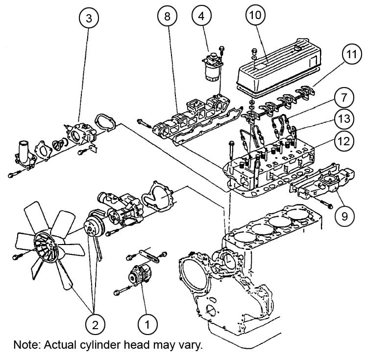
2.Remove the fan (2), pulley (2) and V-belt.
3.Remove the thermostat (3) case.
4.Remove the fuel filter (4) and fuel oil piping.
5.Remove the oil level gauge assembly.
6.Remove the oil filter.
7.Remove the fuel injection pipes (7).
8.Remove the intake manifold (8) assembly.
9.Remove the exhaust manifold (9) assembly.
10.Remove the hood assembly (10).
11.Remove the rocker shaft assembly (11), push rods and valve caps.
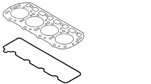
12.Remove the cylinder head assembly (12) and head gasket.
13.Remove the fuel injection valves and fuel return pipe (13).
14.Remove the intake/exhaust valves, stem seals and valve springs.
15.Remove the rocker arms from the rocker shaft.
DisassemblingtheFour-HeadCylinder
For a larger view of Figure 5-111, see Figure 5109 on page265.
2.Install the intake/exhaust valves, stem seals and valve springs.
3.Install the fuel injection valves and fuel return pipe (13).
4.Install the cylinder head assembly (12) and head gasket.
5.Install the rocker shaft assembly (11), push rods and valve caps.
6.Install the hood assembly (10).
7.Install the exhaust manifold (9) assembly.
8.Install the intake manifold (8) assembly.
9.Install the fuel injection pipes (7).
10.Install the oil filter.
Figure 5-110 Cylinder Head Loosening/Tightening Order
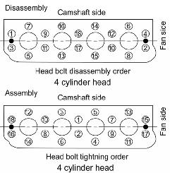
1.Loosen the cylinder head bolts (M13 x 1.5) as shown. See Figure 5-110.
2.Position the cylinder head assembly onto a clean work surface to prevent any damage to the combustion face.
AssemblingtheCylinderHead
11.Install the oil level gauge assembly.
12.Install the fuel filter (4) and fuel oil piping.
13.Install the thermostat (3) case.
14.Install the fan (2), pulley (2) and V-belt.
15.Install the oil cooler (1) and alternator assembly.
AssemblingtheFour-HeadCylinder
1.Replace the head gasket with a new head gasket.
2.Apply oil onto cylinder head bolts (M13 x 1.5) threaded and seat portions.
3.Install cylinder head bolts (M13 x 1.5).
4.Tighten cylinder head bolts (M13 x 1.5) to tightening torque 133.8-141.0 lb.-ft. (181.4191.2 Nm) as shown. See Figure 5-110.
Figure 5-111 Cylinder Head Components
1.Install the rocker arms onto the rocker shaft. See Figure 5-111.
ServicingtheGearTrainand Camshaft
DisassemblingtheGearTrainandCamshaft
11.Remove the PTO lubrication pipe (8).
12.Remove the starting motor (9).
13.Remove the flywheel (10).
14.Remove the camshaft assembly (11). See “Disassembling the Camshaft” on page269 and “Inspecting the Camshaft” on page270.
15.Remove the gear case (12).
16.Remove and discard the oil seal (13) from the gear case cover.
AssemblingtheGearTrainandCamshaft
1.Apply lithium grease to a new oil seal (13). See Figure 5-112.
2.Install oil seal (13) onto the gear case cover.
3.Apply Yanmar sealant No. 977770-01212 to the gear case.
Components
Disassemble the gear train and camshaft according to the following steps and as shown in Figure 5112.
1.Complete cylinder head disassembly procedure steps 1 through 12. See “Disassembling the Cylinder Head” on page265.
2.Remove the water pump (2). See Figure 5-112.
3.Remove the mounting bolt (14).
4.Using a gear puller, remove the crankshaft pulley (3).
IMPORTANT:Use a pad and work carefully. Do not damage the thread or pulley.
5.Remove the gear case cover (4).
6.Remove the fuel injection pump drive gear mounting nut (16).
7.Using a gear puller, remove the fuel injection pump drive gear (15).
IMPORTANT:Use a pad and work carefully. Do not damage the thread or drive gear.
8.Remove the fuel injection pump (5).
9.Remove the idle gear assembly (6).
10.Remove the PTO drive gear (7).
4.Install gear case (12) by matching the two dowel pins.
5.Install the oil pan mounting bolts onto the bottom side of the gear case.
6.Install the camshaft assembly (11). See “Assembling the Camshaft” on page271.
7.Install the flywheel (10).
8.Install the starting motor (9).
9.Install the PTO lubrication pipe (8).
10.Install the PTO drive gear (7).
11.Install the idle gear assembly (6).
12.Install the fuel injection pump (5).
13.Install the fuel injection pump drive gear (15).
14.Install the fuel injection pump drive gear mounting nut (16).
15.Install the gear case cover (4).
16.Install the crankshaft pulley (3).
17.Install the mounting bolt (14).
18.Install the cooling water pump (2).
19.Complete cylinder head assembly procedure steps 4 through 15. See “Assembling the Cylinder Head” on page266.
DisassemblingtheCrankshaftPulley
1.Remove the mounting bolt.
2.Securely position the gear puller to prevent the crankshaft pulley from being damaged.
3.Using a gear puller, remove the crankshaft pulley.
IMPORTANT:Use a pad and carefully operate when removing the crankshaft pulley so as not to damage the thread.
AssemblingtheCrankshaftPulley
NOTICE: Do not to damage the oil seal while assembling the crankshaft pulley.
1.Apply lube oil to the mounting bolt. Only apply enough oil to assist with tightening the mounting bolt.
2.Install the crankshaft pulley.
IMPORTANT:Use a pad and carefully operate when installing the crankshaft pulley so as not to damage the thread.
3.Install the mounting bolt.
4.Tighten the mounting bolt to tightening torque 79.6-94.0 lb.-ft. (107.9~127.5 Nm).
AssemblingtheGearCaseCover
NOTICE: Be sure to install the two reinforcing bolts at the center when installing the gear case cover.
Figure 5-113 Gear Train
1.Measure the backlash of each gear (mm). See Figure 5-113 and the following table.
Crankshaft gear, Camshaft gear, Fuel injection pump gear, Idle gear, PTO gear, Lubricating oil pump gear0.09~0.150.17
2.Apply sealant to the gear case cover.
3.Install the gear case cover by correctly positioning the two dowel pins.
DisassemblingtheFuelInjectionPump
1.Remove the fuel injection pump drive gear mounting nut.
2.Using the gear puller, remove the gear.
IMPORTANT:Use a pad at the shaft and carefully operate when removing the gear. Do not damage the thread.
3.Remove the fuel injection pump.
NOTICE: Be sure to remove the stay on the rear side.
AssemblingtheFuelInjectionPump
1.Install the fuel injection pump.
NOTICE: Be sure to install the stay on the rear side.
2.Install the gear.
IMPORTANT:Use a pad at the shaft and carefully operate when installing the gear. Do not damage the thread.
3.Install the fuel injection pump drive gear mounting nut.
4.Tighten the drive gear nut to tightening torque 61.5-68.7 lb.-ft. (83.4-93.2 Nm).
AssemblingtheGearTrain
DisassemblingtheCamshaft
Figure 5-114 Gear Train
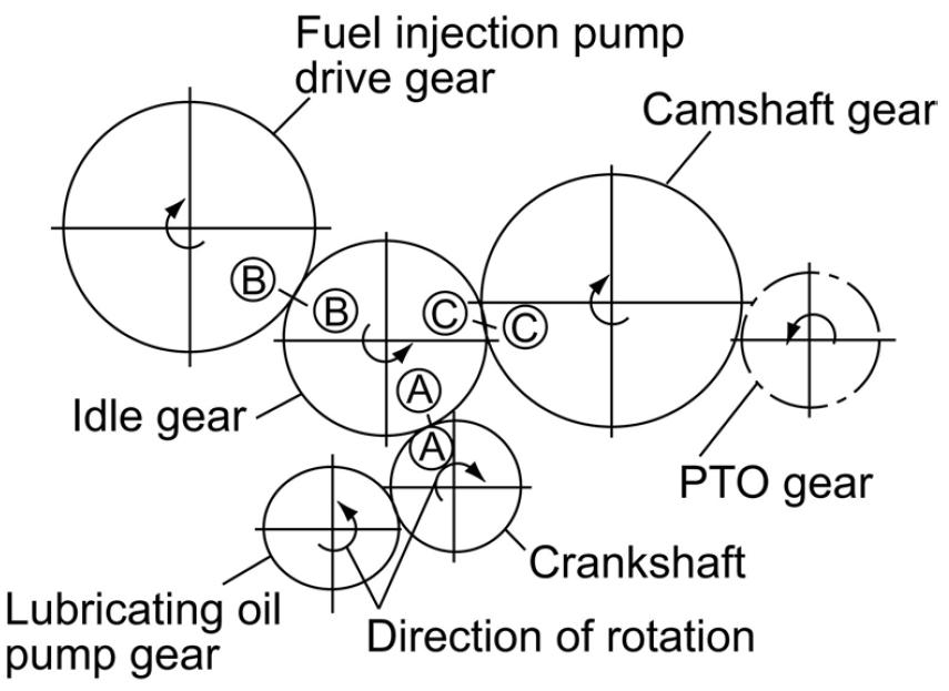
1.Simultaneously assemble crankshaft gear A, fuel injection pump drive gear B and camshaft gear C by installing them onto idle gear A, B and C marks. See Figure 5-114.
2.Install the idle gear shaft with the oil hole facing upward.
3.Install the PTO drive gear with its inner spline side facing the flywheel.
DisassemblingtheFlywheel
1.Install a bolt, to be used as a handle, into the hole at the end face of the flywheel.
2.Carefully remove the flywheel.
NOTICE: Do not damage the ring gear while removing the flywheel.
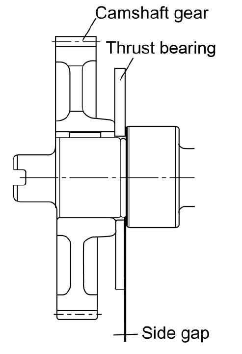
Figure 5-115 Camshaft Side Gap
1.Measure the camshaft side gap (mm). See Figure 5-115 and the following table.
2.If the measured side gap exceeds the limit, replace the thrust metal.
Danger
Afterheatingcrankshaftgearto356°F~392°F (180°C~200°C),severeburnscanoccur.Proceedwithextremecaution.
3.Because the camshaft gear is shrink-fit, heat the camshaft gear to 356°F~392°F (180°C~200°C) before removing.
4.Raise the engine with its mounting flange at the bottom.
5.Remove the thrust metal mounting bolt from the camshaft gear hole.
6.Rotate the camshaft four turns before removing it to prevent the tappet from being caught by the cam.
7.Remove the camshaft carefully.
NOTICE: Do not to damage the bearing bushing.
8.Position the engine horizontally and secure it onto the base.
Caution
Injuriesmayresultwhenraisingtheengineverticallyorreturningittothehorizontalposition. Proceedcarefullysoasnottolosebalance.
InspectingtheCamshaft
CheckingforCamshaftBend
1.Check the contact between the tappet and camshaft contact surface, bearing seizure and wear, and gear damage.
MeasuringtheCamshaftOutsideDiameter
MeasuringtheCamshaftBend
1.Support the camshaft with V-blocks. See Figure 5-116.
2.Rotate the camshaft.
3.Using a dial gauge, measure runout at the center of the camshaft and at each plain-bearing shaft. See Figure 5-116.
4.Half (1/2) of the runout measured is the bend. Compare measurements made to the following table:
6.Using a micrometer, measure and write down the camshaft outside diameter. See Figure 5117.
7.Insert the camshaft bushing into the cylinder.
8.Using a cylinder gauge, measure and write down the camshaft bushing inside diameter
9.Use the following equation to calculate oil clearance: oil clearance = camshaft bushing inside diameter - camshaft outside diameter
5.Compare intake-exhaust camshaft height measurements to the following table:
ME12002YANMARENGINE4TNE106T-NS(SNAB00473-AB03158)
MeasuringtheGears
InspectingtheIdleGear
1.Check the bushing seizure, wear, and gear damage.
InspectingthePTODriveGear
1.Check for bearings sticking on both sides.
2.Check for gear damage and looseness.
3.Check for gear shaft damage and wear.
ReplacingtheOilSeal
1.Replace the oil seal with a new oil seal when disassembling the gear case.
2.Apply lithium grease.
AssemblingtheCamshaft CAUTION
Injuriesmayresultwhenraisingtheengineverticallyorreturningittothehorizontalposition. Proceedcarefullysoasnottolosebalance.
1.Position the engine horizontally and secure it onto the base.
NOTICE: Do not to damage the bearing bushing.
2.Raise the engine with its mounting flange at the bottom.
3.Install the camshaft carefully.
4.Install the thrust bearing mounting bolt into the camshaft gear hole.
2.Measure and write down the shaft outside diameter and bushing inside diameter. See Figure 5-118.
3.Compare shaft outside diameter and bushing inside diameter measurements to the following table:
DisassemblingtheCylinderBlock RemovingtheMountingFlange
1.Complete cylinder head disassembly procedure steps 1 through 12. See “Disassembling the Cylinder Head” on page265.
2.Complete gear train and camshaft disassembly procedure steps 2 through 15. See “Disassembling the Gear Train and Camshaft” on page267.
3.Remove the oil pan (3). See Figure 5-120.
IMPORTANT:Do not damage the oil pan bonding surface.
4.Remove the lubricating oil suction pipe (4).
5.Install the camshaft gear. See Figure 5-119. ServicingtheCylinderBlock

Caution
Injuriesmayresultwhenraisingtheengineverticallyorreturningittothehorizontalposition. Proceedcarefullysoasnottolosebalance.
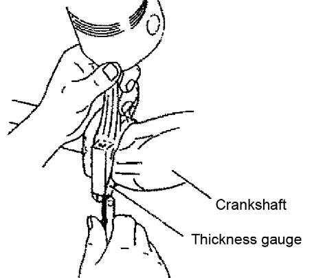
5.Measure the connecting rod side gap. The measurement should be 0.20 ~ 0.40 mm. See Figure 5-121.
6.Wipe-off any carbon deposits on top of the cylinder.
IMPORTANT:Do not damage the inner surface of the cylinder.
7.Rotate the piston (5) to the bottom dead center position and remove the connecting rod cap. See Figure 5-122.
For servicing the piston, see “Servicing the Piston” on page279.
8.Rotate the piston to the top dead center position and push the connecting rod wide-end with the shaft of a hammer.
NOTICE: Do not allow the cylinder block to collide with the connecting rod wide-end.
9.Return the rod caps and crank-pin bearings to their correct combinations.
10.Position the engine with the cylinder block upper surface facing downward and secure it onto a base.

11.Remove the mounting flange (6). See Figure 5122.
12.Remove and discard the mounting flange (6) oil seal.
IMPORTANT:Do not damage the combustion surface when removing the mounting flange.
RemovingtheCrankshaft
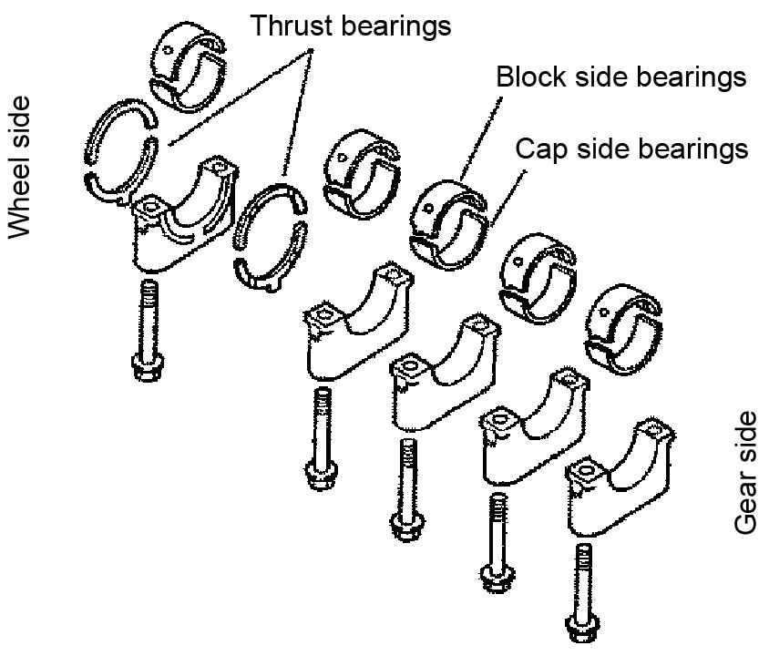
2.Remove the bearing caps (7) and cap side bearings. Identify and position upper and lower bearings as pairs. The upper bearing has an oil hole. See Figure 5-123 and Figure 5-124.
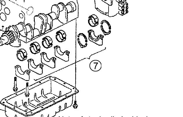
3.Remove the thrust bearings. Identify and position each thrust bearing in the direction of removal. See Figure 5-125.
Caution
1.Measure the crankshaft side gap. The crankshaft side gap should measure 0.13~0.23 mm. If the side gap exceeds 0.23 mm, replace the thrust bearing with a thrust bearing exceeding 0.1” (2.605 mm) thickness.
Usecarewhenmovingthecrankshaft,mishandlingthecrankshaftcancauseseriousinjury, anddamagetothecrankshaft.
4.Remove the crankshaft (8). Identify and position each upper bearing with each cap side lower bearing. See Figure 5-120. For servicing the crankshaft, see “Servicing the Crankshaft” on page277.

RemovingPistonPinandRings
InspectingandMeasuringCylinder BlockParts
1.Inspect the cylinder bore for discoloration and/ or cracking. If there is the appearance of cracking, confirm cracking by performing a colorcheck.
2.Wipe-off all carbon deposits and bonding agents.
3.Clean the cylinder head surface, cylinder bores and oil holes.
4.Check that the oil holes are not clogged.
1.Remove the piston rings. See Figure 5-127.
2.Remove the circlip and remove the piston pin by pushing it out.
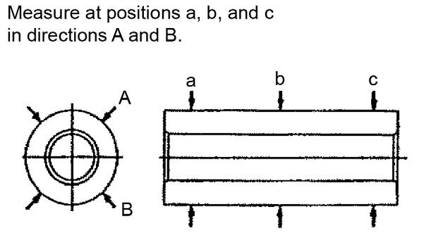
5.Check for cylinder bore distortion by measuring at 20 mm below the liner crest and 20 mm above the bottom end of the cylinder. Measure in the center as shown. See Figure 5-129.
6.Measure in two directions, A and B, at points a, b, and c. See Figure 5-130.
7.Refer to the following table for acceptable measurements:
3.Remove and discard oil seal (11). See Figure 5-120.


*roundness: Maximum value of the difference between the measured values in the same cross section.
*cylindricity: Maximum value of the difference between the measured values in the same direction.
8.If measurements are not acceptable (see step 7 for acceptable measurements), repair or replace as required. When replacing, use an oversized piston and new piston rings as required. Refer to the following table for acceptable measurements:
InstallingPistonPinandRings
1.Apply standard lube oil to the sliding contact surfaces of the pistons, rods, and rings.
AssemblingtheCylinderBlock
3.Install the piston ring joints as shown. See Figure 5-134.
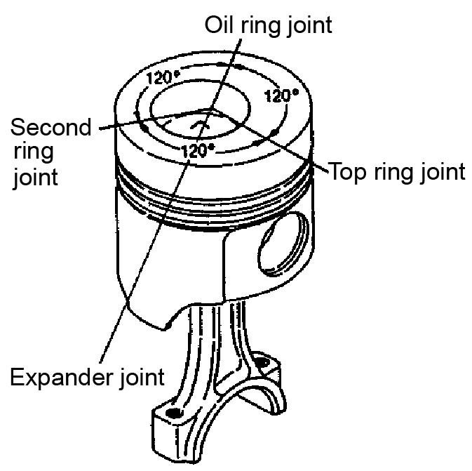
NOTICE: Do not position the top ring joint vertical to the piston pin.
1.Install the crankshaft (8). See Figure 5-136.
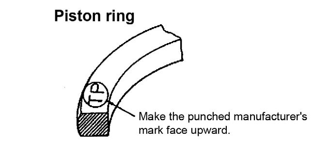
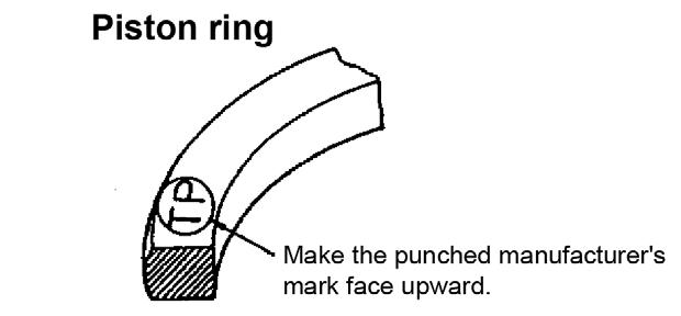
4.Install each piston ring onto the piston with the manufacturer’s mark facing upward. See Figure 5-135.
InstallingtheCrankshaft
Caution
Usecarewhenmovingthecrankshaft,mishandlingthecrankshaftcancauseseriousinjury, anddamagetothecrankshaft.
2.Install the bearing caps (7), cap side bearings, and upper and lower bearings as pairs. The upper bearings have oil holes. See Figure 5137 and Figure 5-138.
3.Install the thrust bearings in the direction of removal. See Figure 5-138.
Caution
Injuriesmayresultwhenraisingtheengineverticallyorreturningittothehorizontalposition. Proceedcarefullysoasnottolosebalance.
NOTICE: Do not damage the combustion surface when installing the mounting flange.
1.If necessary, position the engine with the cylinder block upper surface facing downward and secure it onto a base.
2.Apply lithium grease to and install a new oil seal.
3.Apply Yanmar sealant No. 977770-01212 to and install mounting flange (6). See Figure 5139.
4.Install the rod cap and crank-pin bearing combinations.
IMPORTANT:Do not allow the connecting rod wide-end to collide with the cylinder block.
5.If necessary, rotate the piston (5) to the top dead center position and install the connecting rod wide-end.
6.If necessary, rotate the piston to the bottom dead center position and install the connecting rod cap.
7.Install the lubricating oil suction pipe (4).
8.Apply Yanmar sealant No. 977770-01212 to the oil pan and install the oil pan (3).
IMPORTANT:Do not damage the oil pan bonding surface.
9.Complete cylinder head assembly procedure steps 1 through 15. See “Assembling the Cylinder Head” on page266.

10.Complete gear train and camshaft assembly procedure steps 1 through 18. See “Assembling the Gear Train and Camshaft” on page267.
ServicingtheCrankshaft
1.If necessary, complete all steps in “Removing the Mounting Flange” on page272 and “Removing the Crankshaft” on page273.
2.Clean the crankshaft.
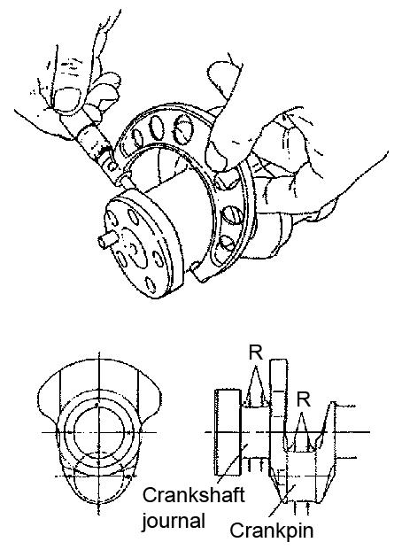
3.Check crankpins/journals for signs of seizure and wear.
Danger
Afterheatingcrankshaftgearto356°F~392°F (180°C~200°C),severeburnscanoccur.Proceedwithextremecaution.
4.Because the crankshaft gear is shrink-fit. Heat the crankshaft gear to 356°F~392°F (180°C~200°C) before removing.
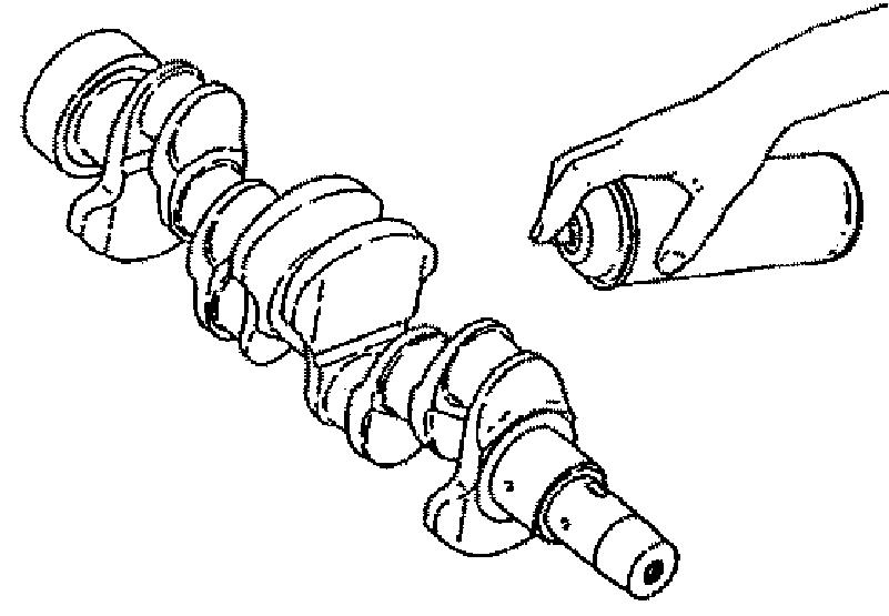
5.Color-check the crankshaft as shown. See Figure 5-140.
6.Replace the crankshaft if it is cracked or heavily damaged. Correct slight crankshaft defects by grinding.
Figure 5-141 Crankshaft Bend Measurement
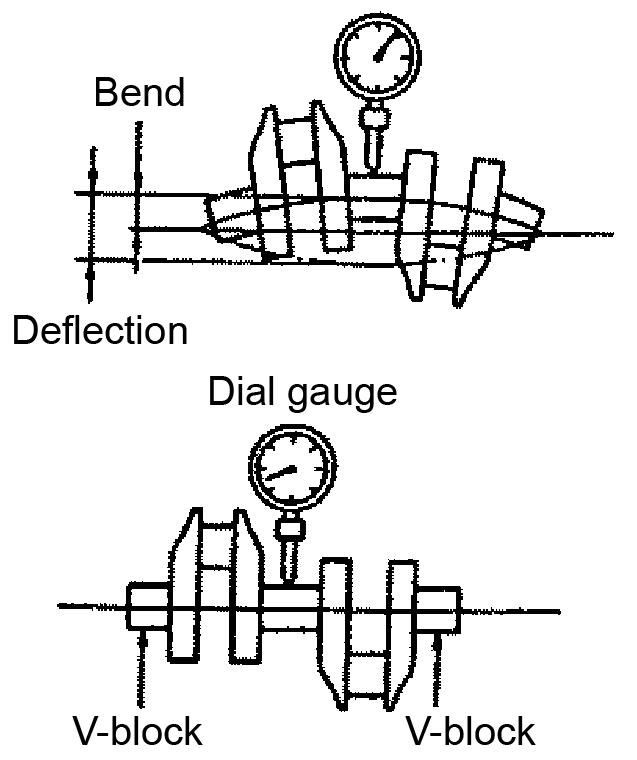
7.Support the crankshaft journals at both ends with V-blocks. See Figure 5-141.
8.While rotating the shaft, use a dial gauge and measure the center journal runout.
9.While rotating the shaft, measure the crankshaft bend. The bend must be 0.02 mm or less.
5-142 Crankpin and Crank Journal Measuring Position
10.Measure the outside diameter, roundness, and taper at each crankpin and crankshaft journal as shown. See Figure 5-142.
NOTICE: If the oil clearance is excessive and the journal and crankpin metal thicknesses are normal, or if there is partial, uneven wear, re-grind the crankshaft and use oversized bearings.
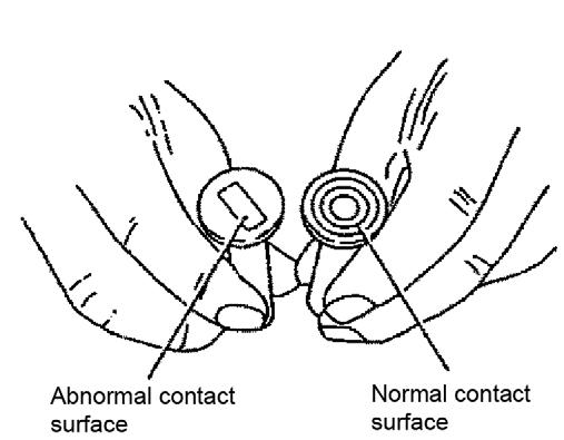
NOTICE: If rust or surface roughening exists on the rear side of the bearing, coat it with engineer’s blue or equivalent. Then assemble the crankpin metal to the connecting rod and tighten the rod bolt to the specified torque to check the metal for contact. If there is 75% or more surface contact, the metal is normal. If there is less than 75% surface contact, replace the metal.
11.Replace the crankpin and/or crankshaft journal if the roundness exceeds the limit or is below the standard range. Correct uneven wear by grinding. Refer to the table on the following page.
12.Replace the bearing if the oil clearance exceeds the limit or is below the standard range. Refer to the table on the following page.
13.Replace the crank journal bearing if the diameter exceeds the limit or is below the standard range. Refer to the following table.
ServicingthePiston
1.If necessary, complete all steps in “Removing the Mounting Flange” on page272 and “Removing Piston Pin and Rings” on page274.
2.Clean the combustion surface, circumference, ring grooves, piston pin bosses, and wipe-off any carbon deposits.
3.Remove any debris from the ring and snap ring grooves. If there may be a crack, inspect the ring and snap ring grooves by performing a color-check.
14.Check the thrust bearings for any damage or wear and for appropriate thickness. Refer to the following table.
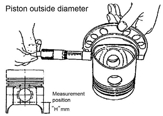
Figure 5-143 Piston Outside Diameter
4.Measure the piston length from the bottom end of the piston oval hole to the piston pin hole at the measurement position marked “H” mm in Figure 5-143.
5.Check that measurement position “H” is 30 mm.
15.If the side gap is exceeded, use an oversized thrust bearing measuring 2.555~2.605 mm.
16.If necessary, complete all steps in “Installing the Mounting Flange” on page277 and “Installing the Crankshaft” on page276.
6.Measure the piston outside diameter. The standard piston outside diameter measurement is 105.930~105.960 mm and the limit is 105.880 mm.
7.Measure the clearance between the piston and the cylinder. If the clearance exceeds 0.080 mm, use an oversized piston (0.25 mm). The oversized piston (0.25 mm) diameter should equal 106.250 mm.
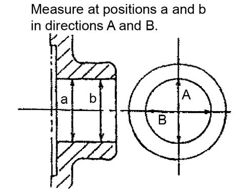
8.Measure the piston pin outside diameter at positions a, b, and c in directions A and B. See Figure 5-144. The piston pin outside diameter measurement should equal 106.250~106.280 mm.
10.Measure the top ring, ring groove, and end clearance measurement. See Figure 5-146. Refer to the following table.

9.Measure the piston pin hole diameter at positions a and b in directions A and B. See Figure 5-145. Refer to the following table for acceptable piston pin hole diameter measurements.
11.Measure the width of the piston ring. See Figure 5-147.
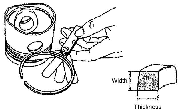
12.Insert the piston ring into the ring groove.
13.Measure the side clearance by inserting a thickness gauge between the piston ring and ring groove.
14.Use the following equation to calculate the ring groove width: ring groove width = ring width + measured side clearance
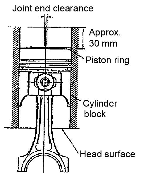
Figure 5-148 Ring Joint End Clearance Measurement
15.Using the piston head, push the piston ring into the sleeve to about 30 mm above the bottom end of the cylinder.
16.Measure the end clearance by inserting a thickness gauge into the end clearance. Refer to the following table.
17.Measure the oil ring, ring groove, ring width, side clearance, and end clearance measurement. See Figure 5-148. Refer to the following table.
InspectingtheConnectingRod
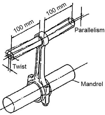
Figure 5-149 Twist Parallelism Measurement
1.Inspect the connecting rod near the chamfered portion and I-beam section of the big and small connecting rod ends. See Figure 5-149.
2.Inspect the connecting rod near the oil hole of the bushing at the small end for cracks, deformation, and discoloration.
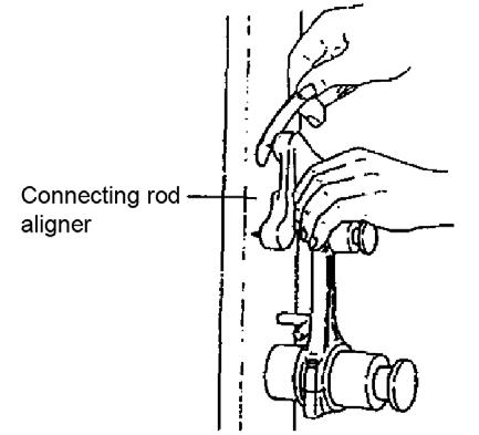
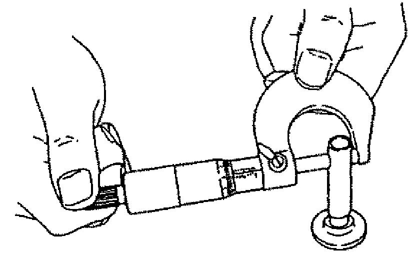
5-150 Connecting Rod Aligner Twist Measurement
3.Using a connecting rod aligner, measure the connecting rod twist and bend. The measurement should be 0.03 mm or less per 100 mm, with a limit of 0.08 mm per 100 mm. See Figure 5-150.
4.Using a cylinder gauge, measure the connecting small rod pin inner and outer diameter. See Figure 5-151, Figure 5-152, and refer to the following table.
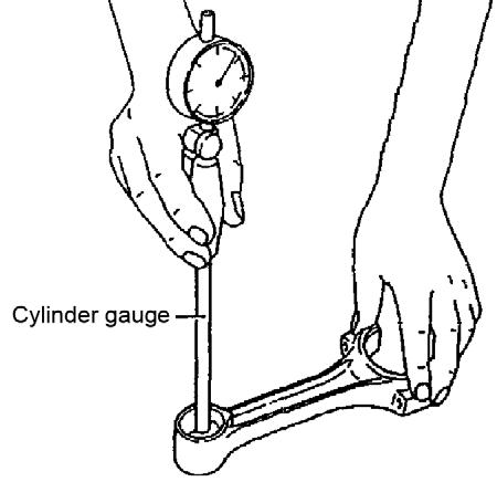
Piston pin inner diameter bushing37.025~37.03837.068
Pin outer diameter36.989~37.00036.961 Clearance0.025~0.0490.107
5.Measure the outside diameter, roundness, and taper of the connecting big rod end crankpin and bushing.
InspectingtheTappet
3.Measure the tappet stem outside diameter as shown. Refer to the following table.
Tappet hole inner diameter14.000~14.01814.038 Stem outer diameter13.966~13.98413.946 Clearance0.015~0.0520.092
1.Inspect the tappet contact surface, this is the surface that contacts the camshaft and push rod. See Figure 5-152.
2.Using an oilstone, correct any minor tappet contact surface defects as necessary.
4.Prepare the following items for honing: FlexHone, electric drill, and honing fluid. Honing fluid consists of 50% lube oil and 50% diesel oil. See Figure 5-154.
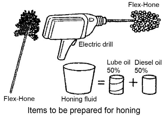
5.Insert the Flex-Hone into the electric drill.
6.Correct slightly unevenly worn, and otherwise minorly flawed cylinder bores by honing.
For cylinder bores that cannot be repaired only by honing, re-bore the cylinder bore first and then hone the cylinder bore.
Replace cylinder bores that contain major flaws.
7.Apply the honing fluid to the Flex-Hone and warm-up the electric drill to about 300-1200 rpm.
IMPORTANT:Do not exceed 1200 rpm, otherwise damage may occur.
8.Dip the Flex-Hone, attached to the electric drill, into the honing fluid.
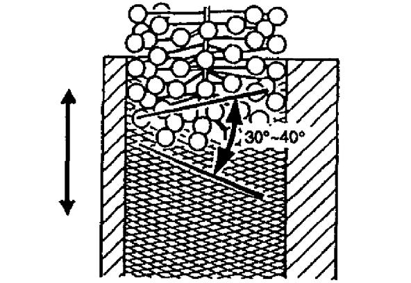
5-155 Honing Cross Hatch
9.Insert the Flex-Hone into the cylinder bore while rotating the Flex-Hone and moving the electric drill up-and-down for approximately 30 seconds. This process obtains a honing mark with a cross-hatch angle of 30-40°. See Figure 5-155.
IMPORTANT:Do not insert or extract FlexHone into cylinder bore unless the Flex-Hone is rotating, otherwise the cylinder may be damaged.
ServicingtheTrochoidPump
RemovingtheTrochoidPump
5.Remove the lubricating oil pump assembly (4) from the gear case. See Figure 5-160.
1.Loosen the belt and remove the fan, pulley and V-belt. See Figure 5-158.
For a larger view of Figure 5-158, see Figure 5-109 on page265.
6.Remove the pressure regulating valve (5) from the lubricating oil pump.
7.Wash the pressure regulating valve.
8.Only disassemble the pressure regulating valve if there is any abnormal operation.
InspectingtheTrochoidPump
2.Using a gear puller, remove the crankshaft pulley (3). See Figure 5-159.
IMPORTANT:Use a pad and work carefully. Do not damage the thread or pulley.
3.Remove the gear case cover (4).
4.Check if the pump rotates smoothly and see that there is no play between the shaft, gear, and inner rotor.
1.Measure the oil clearance between the outer rotor and gear case as shown. The oil clearance should measure 0.100~0.165 mm with a limit of 0.25 mm. See Figure 5-161.
2.Measure the side clearance as shown, the side clearance should measure 0.05~0.10 mm with a limit of 0.15 mm.
2.Install the pressure regulating valve (5) into the lubricating oil pump. See Figure 5-164.
3.Install the lubricating oil pump assembly (4) into the gear case.
NOTICE: If replacing the lubricating oil pump, replace the entire lubricating oil pump assembly.
NOTICE: Always check that the lubricating oil pump rotates smoothly after installation onto the gear case.
3.Measure the rotor shaft outer diameter, the gear case bearing inner diameter, and the gear case clearance as shown. Refer to the following table.
Standard(mm)Limit(mm)
Shaft outer diameter12.955~12.97012.945
Bearing inner diameter12.980~13.02013.050
Clearance0.010~0.0650.105
InstallingtheTrochoidPump
1.If the pressure regulating valve was disassembled (see step 8 of “Removing the Trochoid Pump” on page285), assemble the pressure regulating valve.
4.Install gear case cover (4). See Figure 5-165.
5.Install crankshaft pulley (3).
IMPORTANT:Use a pad and work carefully. Do not damage the thread or pulley.
a larger
No.PartName
1Turbine shaft
2Oil thrower
3Turbine side seal ring
4Seal plate
5Journal bearing
6Thrust bearing
7Compressor housing
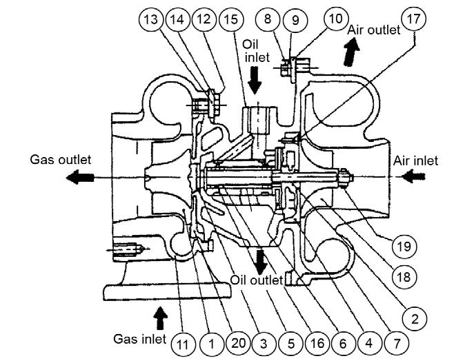
8M5 hexagon bolt
9M5 spring washer
10Compressor side clamp
11Turbine housing
12M6 hexagon bolt
13Turbine side clamp
14Lockwasher
15Bearing housing
16Retaining ring
17M3 countersunk flat head screw
18Compressor wheel
19Shaft end nut
20Heat protector
TurbochargerOverview
Turbine
The turbine includes a seal ring and heat insulating plate to protect the bearing. In the turbine, engine exhaust gas accelerates within the turbine housing nozzle portion and blows into the turbine impeller to rotate the turbine shaft.
Compressor
The turbine shaft compressor impeller rotates with the shaft to suck and compress air for feeding into the intake manifold.
CompressorSideSealingMechanism
A seal ring and seal plate are provided to prevent the intake air and oil from leaking and to form a double wall structure on the rear side of the compressor impeller.
Bearings
ThrustBearing
A thrust force constantly pressures the turbine shaft, the thrust bearing prevents the thrust force from moving the turbine shaft.
RadialBearing
A floating bearing is adopted. Because the bearing moves with the turbine shaft as oil films form both inside and outside of the bearing, the bearing sliding speed is slower than the turbine shaft speed, resulting in higher dynamic stability.
WasteGate
The waste gate consists of a control assembly separated from the turbocharger and a valve assembly installed in the turbine impeller chamber.
When blower side pressure (intake air pressure) exceeds the specified level, turbine inlet exhaust gas partially bypasses to the exhaust discharge side. This controls the turbine rpm which maintains intake pressure at the specified level. The maintained intake pressure improves the response to load variation in the low to medium speed range and minimizes black smoke generation.
TurbochargerComponents
No.PartName
1Turbine shaft
2Thrust bushing
3Oil thrower
4Seal ring
5Seal ring
6Seal ring (turbine side)
7Lock nut
8lmpeller
9Seal plate
10Journal bearing
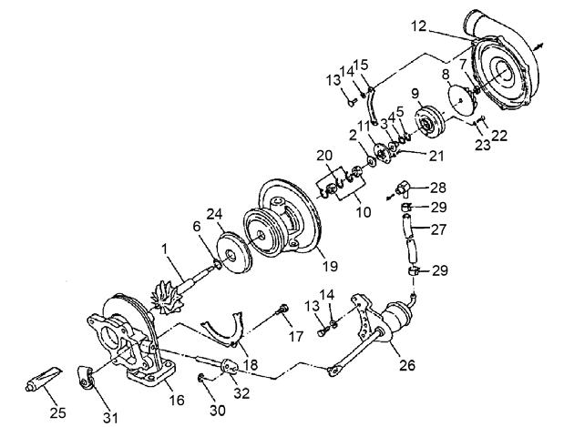
11Thrust bearing
12Compressor housing
13Flanged bolt
14Spring washer
15Clamp
16Turbine housing
17Bolt
18Lock plate
19Bearing housing
20Retaining ring
21Screw
22Screw
23Lock washer
24Heat protector
25Liquid gasket
26Waste gate actuator
27Hose
28Adapter
29Clip
30Retaining ring
31Waste gate valve
32Link plate
CheckingWasteGateValveOpeningPressureandLift
1.Prepare the equipment shown in Figure 5-169, described in the following table:
Dial gauge Measures 0 to 10 mm (a flat head type is recommended).
Manometer Mercury column or electrical type, measures 0-29 psi (0-1500 mm Hg).
Pressure regulating valve Allows gradual adjustment in a range 0-28 psi (0-20 kPa).
Pressure reducing valve

Suppresses the air supply pressure at 71 psi (490 kPa) or less.
Pressure gauge Bourdon tube pressure gauge (0 to 142 psi [980 kPa]).
2.Follow these requirements when completing steps 3-6:
•Set the dial gauge on the actuator rod extension line.
•Check that the piping and joints are leakfree.
•Secure the turbocharger and dial gauge. If using an electric manometer, be sure it has sufficient precision. When using an electric manometer, also use a mercury column type manometer for calibration and daily check.
•Use a very slow operating speed for the pressure regulating valve when increasing/ decreasing manometer control pressure (Pc) near the measuring point. If the 2 mm position is exceeded, restart from the beginning.
•Do not apply over 71 psi (490 kPa) to the actuator.
3.Secure the manometer to the waste gate actuator.
4.Set the manometer control pressure (Pc) to 0 and set the dial gauge to 0.
5.Gradually open the pressure regulating valve and measure the Pc value when the actuator rod is operated by 2 mm.
6.For the hysteresis, allow the rod to move to 3 mm. This gradually closes the pressure regulating valve. Measure the pressure when the rod moves to 2 mm, and calculate the difference from the pressure measured in step 5 above.
PerformingaWasteGateActuatorLeak Test
1.Apply 17 psi (120 kPa) to the actuator for 1 minute.
2.Check the actuator pressure after 1 minute. The actuator is good if the pressure is 16 psi (110 kPa) or greater. If the pressure is less than 16 psi (110 kPa), replace the actuator.
TurbochargerServiceStandards