1 minute read
ME12002HYDRAULICSYSTEM


Port relief valve also functions as a make-up valve. See “Make-up Function” on page117. When an external force acts on a cylinder, hydraulic fluid flow may be insufficient for cylinder velocity. If this occurs, a vacuum and cavitation could develop. Port relief valve fills the vacuum by allowing return hydraulic fluid to flow into the cylinder.
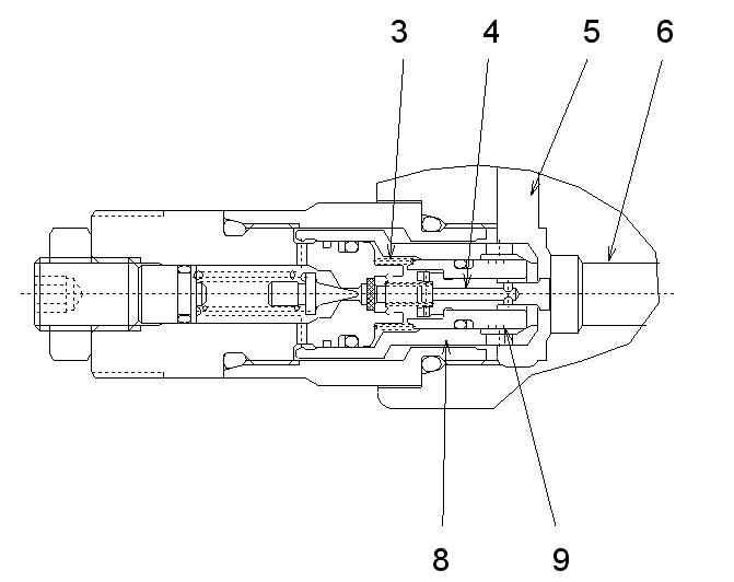
Hydraulic fluid between the cylinder and its spool flows into path (6) to pressurize port relief valve. Hydraulic fluid in path (6) flows through path (4), piston (10), and into spring chamber (3). If spring chamber (3) pressure is lower than the pressure setting, valve washer (2) shuts-off because the force of spring (1) overcomes the pressure. Therefore, path (6) and spring chamber (3) contain the same pressure. See Figure 3-106.
Because spring chamber (3) side pressurized area of seat (8) and plunger (9) is larger than the side pressurized area of path (6), seat (8) and plunger (9) are pressed to the right until they are positioned securely. After seat (8) and plunger (9) are pressed to the right and positioned securely, path (6) hydraulic fluid does not flow into return path (5). See Figure 3-106.
PortReliefFunction
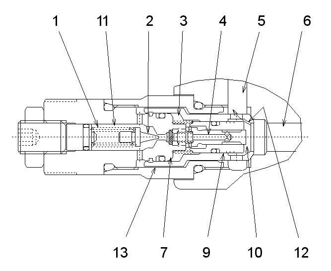
Path (6) hydraulic fluid flows through path (4), piston (10), spring chamber (3) and into chamber (11). While hydraulic fluid flows through path (4), its pressure decreases. While hydraulic fluid flows through spring chamber (3), its pressure decreases and the pressure decrease forces plunger (9) to the left. Path (12) opens and hydraulic fluid from path (6) flows into return path (5). See Figure 3-107.
Make-upFunction
Figure 3-107 Port Relief Function
When path (6) is pressurized to the pressure setting, valve washer (2) is pushed open against spring (1). Hydraulic fluid from chamber (11) flows through path (13) and into return path (5), reducing its pressure. Pressure in path (6) shifts piston (10) to the left until it stops on the end of plug (7). See Figure 3-107.
Figure 3-108 Make-up Function
When a vacuum occurs in path (6) side, it also occurs in path (4) and spring chamber (3). The pressure in the side of return path (5) then presses against seat (8). Return pressure shifts seat (8) to the left because the spring chamber (3) sides of seat (8) and plunger (9) are under a vacuum. Hydraulic fluid in return path (5) flows into path (6), filling the vacuum in path (6) side. See Figure 3-108.


