4 minute read
MAINTENANCEME12002


PurgingAirfromtheFuelSystem: JohnDeereEngineModel4045TF270 (SNAC02633andup)
Warning
DONOTbleedaironahotengine.Spilledfuel cancauseafire.
If the fuel tank is run dry, or if the fuel filter, water separator or fuel lines are replaced, trapped air must be removed, or bled, from the fuel system. Bleed air from the fuel system according to the following steps:
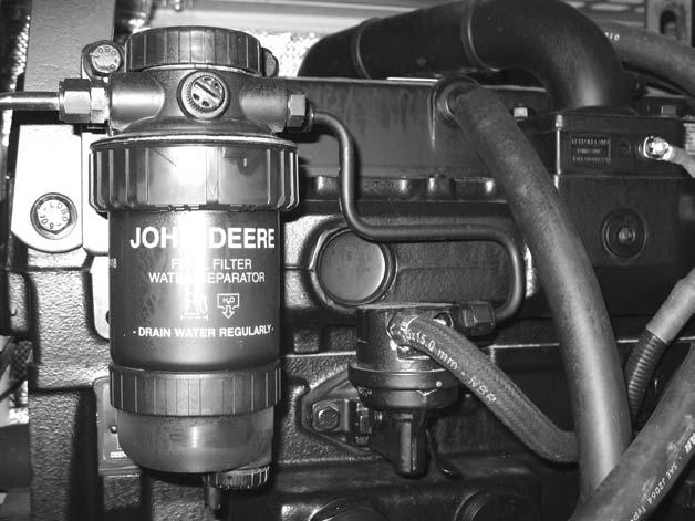
1.Check the fuel filter/water separator for water or dirt, empty it if necessary.
2.Drain and discard water according to local regulations.
6.Actuate the fuel pump backing pump lever (3) until there are no more air bubbles in the fuel. See Figure 2-28.
NOTICE: There should be resistance while performing step 6. If there is no resistance, activate the starter for a few seconds. Do NOT run the engine.
7.Retighten the vent plug (1) and keep operating the fuel pump backing pump lever (3) until the pumping effect is no longer felt. See Figure 228.
8.Press the fuel pump backing pump lever (3) toward the engine as far as possible. See Figure 2-28.
PurgingAirfromtheFuelSystem: YanmarEngineModel4TNE106T-NS (SNAB00473-AB03158)
If the fuel tank has been run dry, or the fuel filter or fuel lines have been replaced, trapped air will have to be removed, or bled, from the fuel system.
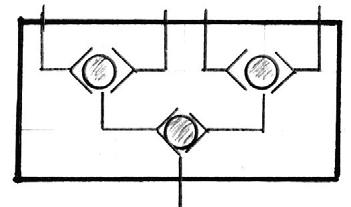
1.Turn the fuel filter valve (Figure 2-29) to the open position (vertical).
2.While operating the priming lever on the fuel injector pump, loosen the air bleeding screw (A, Figure 2-29) on the fuel filter. When fuel starts flowing from the bleeder valve (A) without any air or bubbles, tighten the bleeder screw (A).
3.Repeat step 2 for bleeder screws B, C, D and E (Figure 2-29).
3.Loosen the drain plug (2) at the bottom of the fuel filter/water separator by turning it two or three times. See Figure 2-28.
4.Loosen the vent plug (1) on the fuel filter base by turning it twice. See Figure 2-28.
5.Drain the water from the bottom until fuel starts to run out. As soon as fuel starts to run out, close the drain plug (2) tightly. See Figure 2-28.
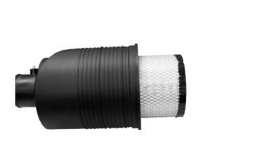
IMPORTANT:Always replace the air filter (B), if the air filter indicator lights up (red), or if the air filter is torn or contaminated at the sides. See Figure 2-32.
3.Move the end of air filter (B) gently to the left and right, and up and down. See Figure 2-32.
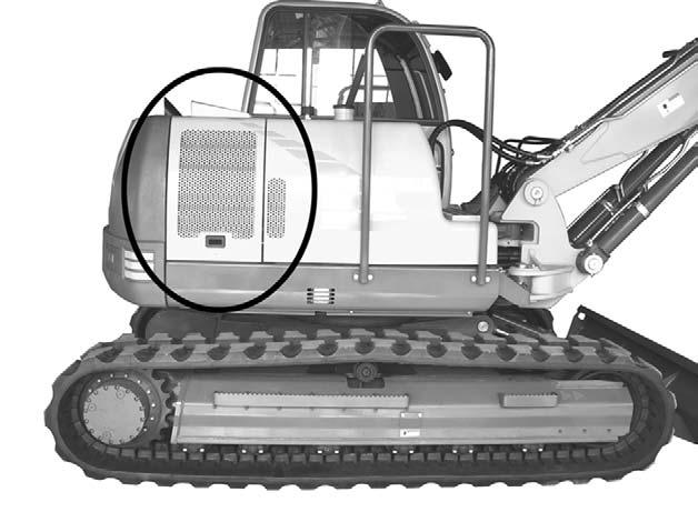
AirCleaner(SNAC02633andup)
IMPORTANT: Do not operate engine without the air cleaner components installed or damage to the engine could occur.
1.Lift the hydraulic tank cover to access the air cleaner. See Figure 2-30.
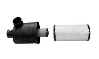
4.Pull air filter (B) out of the outlet pipe and out of the enclosure. See Figure 2-32.
NOTICE:Remove air filter (B) only if replacing it. Do not try to clean, wash, or use it again.
5.Thoroughly clean the inside of the filter housing and the outlet bore.
6.(Optional) To replace safety filter (C), gently pull out the filter element. See Figure 2-33.
IMPORTANT:Remove safety filter (C) only if replacing it. Do not try to clean, wash, or use it again. Usually, the safety filter needs replacement only if there is a hole in air filter (B).
7.(Optional) Install a new safety filter (C) immediately to prevent the penetration of dust into the air intake system. See Figure 2-33.
IMPORTANT:Do not knock the air or safety filters against a solid object to remove dust. The filters may become distorted and/or damaged.
8.Install a new air filter (B). Exert a little pressure with your hand at the outer edge of the filter. See Figure 2-32.
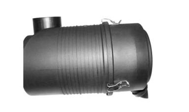
9.Apply and latch the dust collector/cap (A) to the air cleaner. See Figure 2-31.
IMPORTANT:Do not use the latches on the cap to force the filter into the air cleaner housing. Applying force may damage the filter and/ or housing.
NOTICE:Close the housing so that the dust collector valve points downward and the locking mechanism catches.
10.Close and secure the engine cover.
AirCleaner(SNAB03158andbefore)
1.The air cleaner is located under the engine cover. Pull the engine cover latch handle (located on the left side of the operator’s seat) and raise the engine cover.
2.Turn the air cleaner cover bolt (Figure 2-34) to remove the air cleaner cover and gasket.
3.Remove the wingnut (Figure 2-34) and remove air cleaner element.
4.Clean air cleaner element with 30 psi (200 kPa) compressed air. See Figure 2-34.

5.Reinstall air cleaner element, wingnut, gasket, and air cleaner cover. Tighten cover bolt.
6.Close and secure engine cover.
IMPORTANT:Do not knock the element against a solid object to remove dust. The element may become distorted and damaged.
Do not operate engine without the air cleaner element installed or damage to the engine could occur.
CoolantSystem
CheckingCoolantLevel(SNAC02633 andup)
Warning
•Engine must be cold.
•Be careful to avoid burns when removing the cap.
•Keep face away from cap.
•Cover cap with a cloth, turn cap slowly to release pressure.
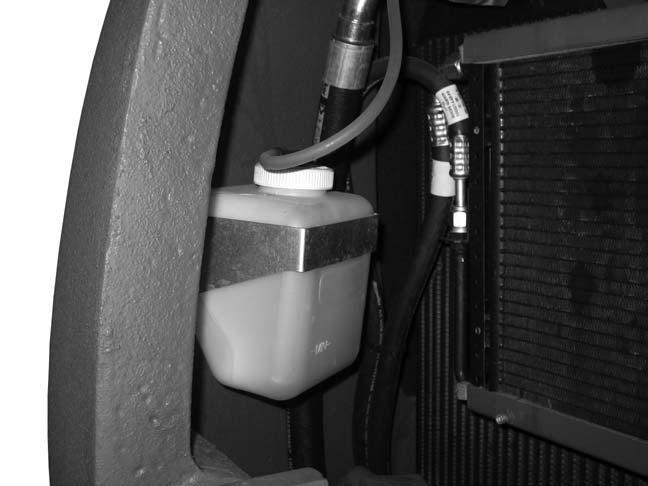
1.Lift the hydraulic tank cover to access the expansion reservoir. See Figure 2-35.
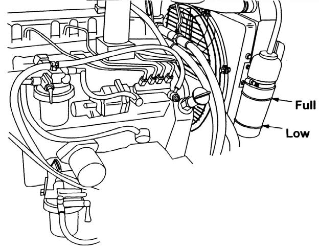
2.Check the coolant level in the expansion reservoir. See Figure 2-36.
3.If low, slowly loosen cap and allow pressure to escape.
4.Completely remove cap and fill reservoir to MAX line.
5.Check the radiator coolant level.
Refer to the engine manual for correct coolant mixture for the engine.
CheckingCoolantLevel(SNAB00473AB03158)
Warning
•Engine must be cold.
•Be careful to avoid burns when removing the cap.
•Keep face away from cap.
•Cover cap with a cloth, turn cap slowly to release pressure.
1.Pull the engine cover latch handle (located on the left side of the operator’s seat) and raise the engine cover.
2.Check the coolant level in the expansion reservoir (Figure 2-37).
3.If low, slowly loosen cap and allow pressure to escape.
4.Completely remove cap and fill reservoir to FULL line.
Refer to the engine manual for correct coolant mixture for the engine.
Chapter3
Hydraulicsystem
NOTICE:For hydraulic system maintenance, see “Hydraulic System” on page30.
HydraulicSystemDiagram
NOTICE:See Figure 3-1 on page52 for hydraulic system diagram.
HydraulicSystemDiagramLegend
1.Diesel engine
2.Variable + gear pump
3.Pilot oil supply unit
4.Joystick left (dipper arm/swivel motor)
5.Joystick right (bucket/boom)
6.Pilot control valve function drive
7.Pilot control valve function boom offset/auxiliary hydraulics
8.Pilot control valve function dozer blade
9.Switch valve function boom offset/auxiliary hydraulics
10.Main valve block
11.Second valve block
12.Drive unit
13.Swivel unit
14.Boom cylinder
15.Dipper arm cylinder
16.Bucket cylinder
17.Dozer blade cylinder
18.Boom offset cylinder
19.Load lowering valve
20.Load retaining counterbalance valve - load lowering valve boom (option)
21.Load retaining counterbalance valve - load lowering valve dipper arm (option)
22.Shuttle valve block
23.Oil cooler
24.Hydraulic oil return filter
25.Leakage oil filter
26.Check valve
HydraulicSystemComponentPositions