3 minute read
HYDRAULICSYSTEMME12002


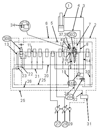
LoweringtheDipperArmCylinder(withlightloads)
After the dipper arm begins excavating, pressure within the head side of arm cylinder (1) increases and presses piston (37) and sub-spool assembly (38) to the right against spring (41). Path (40) opens and most of the return flow from the rod side of arm cylinder (1) flows through arm 1 spool (302), path (40), return path (17) and return path (27) into the tank (the return flow does not flow into the regeneration circuit). See Figure 3-136 and Figure 3-137.
For a larger view of Figure 3-137, see Figure 3-128 on page128.
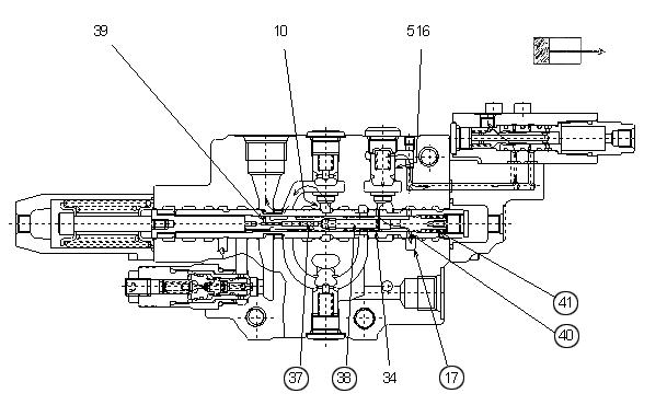
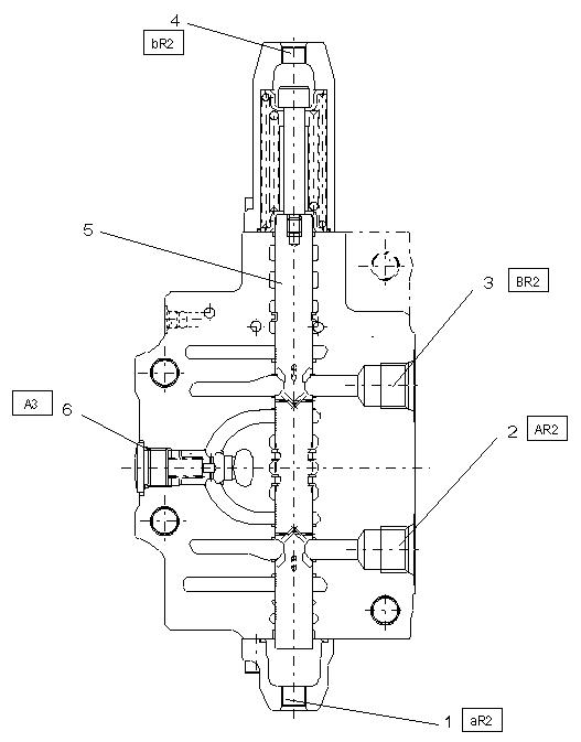
Figure 3-138 Bucket Structure
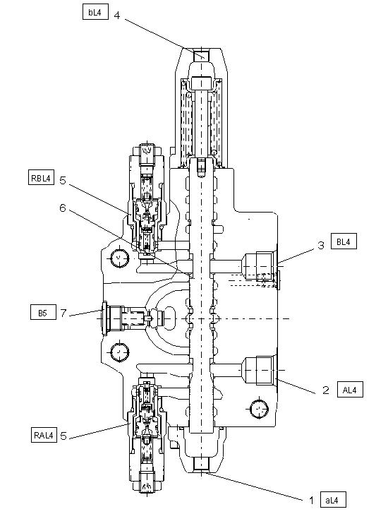
1 Pilot pressure port bucket cylinder extending
2Port bucket cylinder rod side
3Port bucket cylinder bottom side
4 Pilot pressure port bucket cylinder retracting
5 Secondary pressure limiting valve
6Spool bucket
7Direct piloted check valve
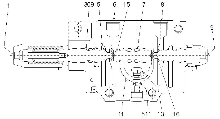
Figure 3-139 Bucket Section
While excavating or releasing the bucket, only front pump (27) supplies hydraulic fluid to the bucket cylinder. Bucket spool (304) reduces the return flow from the bucket cylinder and pump discharge controls the bucket operating speed. See Figure 3-139 and Figure 3-140.
When the pilot control lever is in the neutral position, the pilot control valve does not supply any pilot pressure to either pilot port (1) or pilot port (9). Springs (322) and (328) maintain bucket spool (304) in the neutral position. Front pump (27) hydraulic fluid flows through center bypass (7) and into the tank. See Figure 3-139 and Figure 3-140.
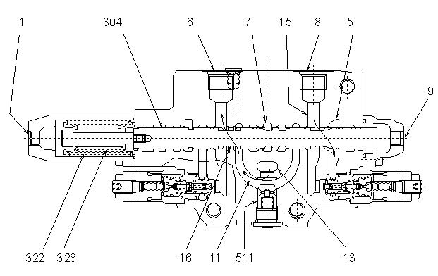
When using the pilot control lever for bucket excavating, pilot pressure is supplied into port (1), shifting bucket spool (304) to the right. Center bypass (7) shuts-off and path (16) opens while path (15) flows into return path (5). See Figure 3-139.
Hydraulic fluid from front pump (27) flows into parallel path (13) and then through load check valve (511), path (11), path (16), and into port (6). See Figure 3-139 and Figure 3-140.
The bucket cylinder extends while the flow from the rod side of the bucket cylinder flows into port (8). Hydraulic fluid then flows through path (15), return path (5), and into the tank. See Figure 3-139.
For a larger view of Figure 3-140, see Figure 3-128 on page128.
1Pilot pressure port
2Port swing motor
3Port swing motor
4Pilot pressure port
5Spool
6Direct piloted check valve
BoomSwingControl
Figure 3-142 Boom Swing Control
While swinging the boom right or left, only rear pump (28) supplies hydraulic fluid into the swing motor. See Figure 3-143.
When the pilot control lever is in neutral position, the pilot control valve does not supply any pilot pressure to either pilot port (1) or pilot port (9). Springs (322) and (328) maintain swing spool (309) in neutral position. Rear pump (28) hydraulic fluid flows through center bypass (7) and into the tank. See Figure 3-142, Figure 3-143 and Figure 3139 on page134.
When using the pilot control lever for swinging the boom right or left, pilot pressure is supplied into port (9), shifting swing spool (309) to the right or left. Center bypass (7) shuts-off and path (16) opens while path (15) flows into return path (5). See Figure 3-142.
Hydraulic fluid flows into parallel path (13) and then through load check valve (511), path (11), path (16), and into port (8). See Figure 3-142.
The swing motor turns to the right or left, depending on the swinging direction, and the return flow from the swing motor flows into port (6). Hydraulic fluid then flows through path (15), return path (5), and into the tank. See Figure 3-142.
Figure 3-143 Dipper Arm Control
For a larger view of Figure 3-143, see Figure 3-128 on page128.
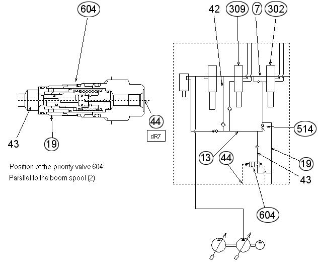
Figure 3-144 Swing Left/Right - Swing Priority Mode
NOTICE:Swing priority valve is shown in an inactive state.
When operating the dipper arm and swing at the same time, swing priority valve (604) operates the swing. See Figure 3-144.
Hydraulic fluid from rear pump (28) flows through parallel path (13) and into swing spool (309) and arm 1 spool (302). Swing spool (309) shifts and shuts-off center bypass (7), causing rear pump (28) to only use parallel path (13) to supply hydraulic fluid into arm 1 spool (302). In swing priority mode, swing priority valve (604) supplies pilot pressure to pilot port (44) and shuts-off path (19).
See Figure 3-144, and for rear pump (28) only, see Figure 3-143 on page136.
Load check valve (514) and its opening restricts the flow from parallel path (13) to arm 1 spool (302). Rear pump (28) then becomes the primary supplier of hydraulic fluid to swing spool (309).
See Figure 3-144, and for rear pump (28) only, see Figure 3-143 on page136.
After exiting swing priority mode, the pilot pressure signal deactivates, shifting the swing priority valve spool and opening path (19). Parallel path (13) hydraulic fluid flows through path (19) and into arm 1 spool (302) of the swing priority valve. See Figure 3-144.
AuxiliaryHydraulicsSection
1,5 Pilot pressure hose spool left/right
2,3Port consumer
4Plug
6 Plug/Secondary pressure limiting valve
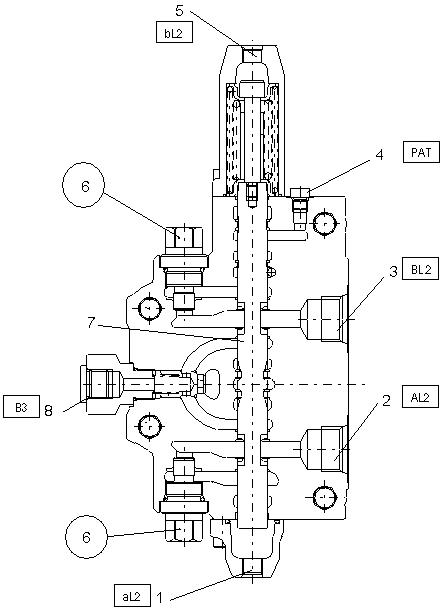
7Spool
8Direct piloted check valve


