1 minute read
OperatingMainRelief


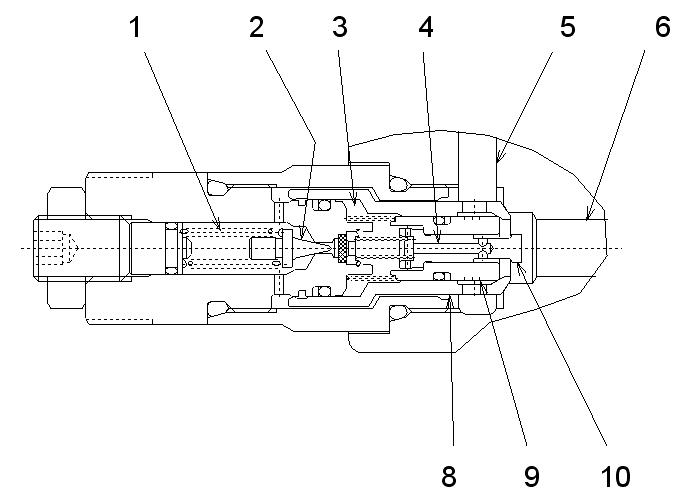
Figure 3-105 Main Relief Operation While Working
While traveling, the force pressing against spring (39) decreases, and the force pressing against valve washer (24) decreases. See Figure 3-105.
When path (13) is pressurized close to the working pressure setting, valve washer (24) opens. Plunger (38) opens and path (13) hydraulic fluid flows into return path (14) to maintain the working pressure setting. Adjustment screw (25) adjusts the working pressure setting. See Figure 3-105.
PortReliefValve
Figure 3-106 Port Relief Valve
Port relief and make-up valves are installed between the cylinders and spools of working components (boom, dipper arm, and bucket). When an external force acts on a cylinder rod, and its spool is in neutral, pressure within the cylinder can become excessive. Port relief valve restricts this pressure to the valve set pressure.


