1 minute read
ME12002HYDRAULICSYSTEM


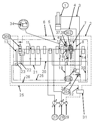
RetractingtheDipperArmCylinder
3-130 Dipper Arm Section (1)
While extending the dipper arm, pilot pressure from pilot control valve (31) flows through pilot line (29), pilot line (24), and shifts arm 1 spool (302) to the left against spring (322) and spring (328). See Figure 3-130 and Figure 3-131.

Hydraulic fluid from rear pump (28) flows into load check valve (511) and through center bypass (10), into path (15), arm lock valve (516) and path (14). Hydraulic fluid then flows into the rod side of arm cylinder (1) through line (3). See Figure 3-130 and Figure 3-131.
For a larger view of Figure 3-131, see Figure 3-128 on page128.
Pilot pressure flows through pilot line (29), pilot line (25), and presses arm 2 spool (308) to the right against spring (322) and spring (329). Arm 2 spool (308) shuts-off center bypass (11), preventing fluid from flowing from center bypass (11) and into return path (13). See Figure 3-132 and Figure 3133.

Hydraulic fluid from front pump (27) combines with hydraulic fluid from rear pump (28) to increase cylinder speed. See Figure 3-133.
Hydraulic fluid flows:
1.Through center bypass (11), path (22) and path (26). See Figure 3-132 and Figure 3-133.
2.Through parallel path (21), arm 2 spool (308), path (23) and into the path (26). See Figure 3132 and Figure 3-133.
3.Total flow supplied into path (26) from front pump (27) flows through path (15) and into path (19). The flow then combines with the total flow from rear pump (28). See Figure 3133.
Return flow from the head side of arm cylinder (1) flows into arm 1 spool (302) through path (4). Return flow then flows through return path (17) and into return line (30). See Figure 3-133.
3-133 Dipper Arm Control
For a larger view of Figure 3-133, see Figure 3-128 on page128.


