1 minute read
ME12002HYDRAULICSYSTEM OperatingPilotPressure


For a larger view of Figure 3-102, see Figure 3-87 on page107.
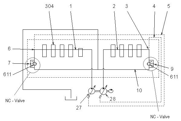
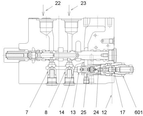
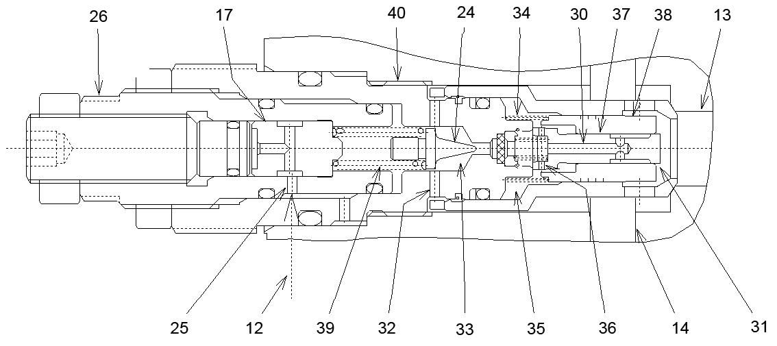
Hydraulic fluid traveling through pilot path (12) pilot pressure connects to piston chamber (17), inside of main relief valve (601). See Figure 3-101 and Figure 3-103. This connection shifts the piston and increases the pressure setting. The flow from pilot pump (21) (not shown) separates at line (10), one portion flows through path (9) and the other portion flows through path (15) (not shown). See Figure 3-102.
For a larger view of Figure 3-103, see Figure 3-98 on page113.

Both path (9) and path (15) (not shown) flow into pilot path (12) as follows: