2 minute read
HYDRAULICSYSTEMME12002


AssemblingtheCover
2.Using a 10 mm hexagon wrench, tighten screws (29), A - B ports (30) and housing (22) to tightening torque 76 lb.-ft. (103 Nm). See Figure 3-300.
AssemblingtheReliefValve
1.Assemble A - B ports (30) and control disk (9) to housing (22), line-up the matching marks made on housing (22) and A - B ports (30) before disassembling. See step 1 of “Marking the Swing Motor” on page190.
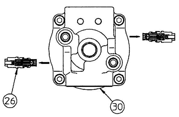
3-301 Relief Valve
1.Using a 27 mm wrench, install and tighten bypass valve (26) onto A - B ports (30) to tightening torque 29 lb.-ft. (39 Nm). See Figure 3-301.
NOTICE:Assemble bypass valve (26) to its original state when reassembling.
CheckingReliefValveAssembly
1.Open inlet and outlet port.
2.Load pilot brake release port pressure to 3-5 MPa (435-725 psi).
3.Check that output shaft is rotating smoothly with a torque of approximately 15-21 lb.-ft. (20-29 Nm).
NOTICE:If output shaft is not rotating, disassemble and check.
4.Open the drain port.
5.Check that relief valves are set to regulation pressure.
Chapter4
JOHNDEEREENGINE4045TF270(SNAC02633ANDUP)
For specifcations, see “John Deere 4045TF270 and Yanmar 4TNE106T-NS Specifications” on page9.
JohnDeereEngineModel4045TF270Overview
ServicingtheComponents
CheckingValveTipClearance
Caution
Beforecompletingthesesteps,disconnectthe negativeterminalbatterycabletopreventthe enginefromaccidentallystartingwhilecheckingthevalvetipclearance.Allowtheengineto cooldownbeforecompletingthesesteps.
NOTICE: Only check the valve clearance after the engine is cold.
1.Remove plug (B) from cylinder head cover (C). See Figure 4-4.
2.Remove the hexagon bolts with O-rings (A) from cylinder head cover (C). See Figure 4-4.
3.Remove cylinder head cover (C). See Figure 44.
4.Remove the crankcase breather tube.
7.Check rocker arms with the following valve tip clearances more thoroughly to detect any damaged parts:
•less than 0.36 mm for intake valve tip clearance, measured from rocker arm to valve tip.
•less than 0.46 mm for exhaust valve tip clearance, measured from rocker arm to valve tip.
8.Replace any damaged parts.
5.Check the contact surfaces of the valve tips and rocker arm for excessive wear, rupture, or cracks.
6.Replace any damaged parts.
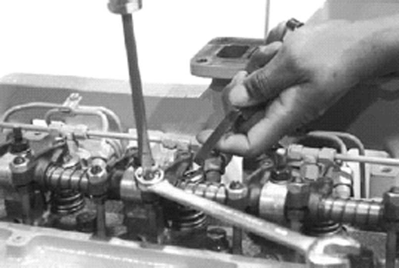
Figure 4-5 Check and Adjust Valve Tip Clearance
9.Remove the plastic plugs/cover plate from the adjustment/rotation opening (D) and the engine adjustment pin opening (E). See Figure 4-5.
10.Use the JDE83 flywheel rotation tool (available directly from John Deere) to turn the flywheel in the direction of rotation (clockwise as seen from the front) until cylinder no. 1 is at the top dead center of the compression stroke. The engine is at the top dead center of the compression stroke of cylinder no. 1 if the rocker arms of cylinder no. 1 can be moved. If the rocker arms of cylinder no. 1 cannot be moved, rotate the engine one full revolution (360°).
11.Insert the JDG1571 or JDE81-4 adjustment pin (available directly from John Deere) into the flywheel.
SettingValveTipClearance
AFront side of engine
B Piston no. 1 at top dead center of compression stroke
C Piston no. 4 at top dead center of compression stroke
EExhaust valve
IIntake valve
NOTICE: The cylinder firing order is 1–3–4–
2.
1.Keep piston no. 1 in place at the top dead center of the compression stroke with the adjustment pin (B). See Figure 4-6.
2.Set the valve tip clearance (rocker arm to valve tip) to 0.46 mm on exhaust valves no. 1 and 3.
3.Set the valve tip clearance (rocker arm to valve tip) to 0.36 mm on intake valves no. 1 and 2.
4.Rotate the crankshaft 360°. Keep piston no. 4 in place at the top dead center of the compression stroke (C). See Figure 4-6.
5.Set the valve tip clearance to 0.46 mm on exhaust valves no. 2 and 4.
6.Set the valve tip clearance to 0.36 mm on intake valves no. 3 and 4.
7.Tighten the rocker arm locknut set screw torque to 20 lb.-ft. (27 Nm) (D). See Figure 47.
ServicingtheCylinderHead
RemovingtheCylinderHead
RemovingtheCylinderHeadCover
Caution
Allowtheengineandexhaustsystemtocool downbeforecompletingthesesteps.
1.Drain the radiator coolant only after it has cooled down to below the operating temperature.
2.Remove the radiator cap only after it has cooled down so that you can touch it with your bare hands.


