3 minute read
HYDRAULICSYSTEMME12002


RaisingtheBoom(highspeedoperation)
During high speed operation, the pilot control lever is fully operated and the spool is fully switched.
SectionBoom(1)
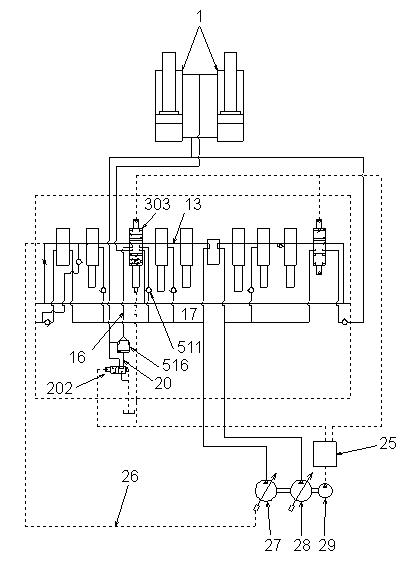
Hydraulic fluid from front pump (27) flows through parallel path (17) and into boom 1 spool (303). Hydraulic fluid from rear pump (28) flows through parallel path (18) and into boom 2 spool (306). See Figure 3-114 and Figure 3-115.
While raising the boom, port (5) senses pilot pressure from pilot control valve (25) and shifts boom 1 spool (303) to the right against springs (322) and (328). See Figure 3-113 and Figure 3-114.
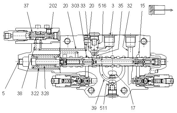
Hydraulic fluid from front pump (27) and from parallel path (17) flows through load check valve (511), path (39) and path (35). The hydraulic fluid then forces open boom lock valve (516), and flows into port (3). Hydraulic fluid then flows through line (6) (not shown) and into the head side of boom cylinder (1). See Figure 3-113 and Figure 3-114.
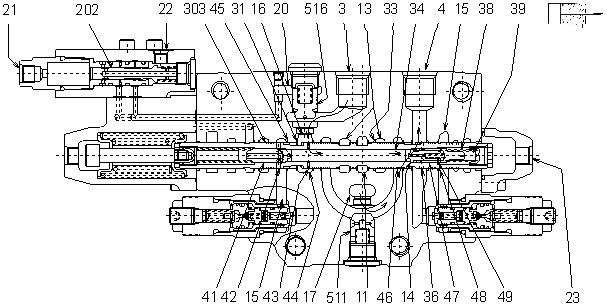
While raising the boom, the path above boom lock valve (516) leads through path (20), sleeve (37) and spool (202) to path (38). Pressure in path (33) opens boom lock valve (516). See Figure 3-113.
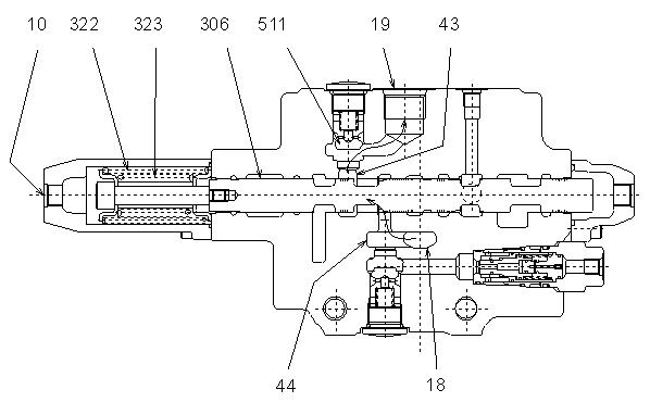
Figure 3-115 Section Boom (2) - Summation
Simultaneously in section boom (2), pilot pressure through port (10) shifts boom 2 spool (306) to the right against springs (322) and (323). The hydraulic fluid of rear pump (28) from parallel path (18) flows into port (19) through path (44), path (43) and check valve (511). See Figure 3-115, and for rear pump (28) only, see Figure 3-116.
Hydraulic fluid flows through line (8), combines with hydraulic fluid from front pump (27), flows into line (6) (not shown), and then flows into the head side of boom cylinder (1). See Figure 3-116, and for boom cylinder (1) only, see Figure 3-111 on page119.
The flow from the rod side of boom cylinder (1) flows through line (7) (not shown) and into boom 1 spool (303). See Figure 3-116, and for boom cylinder (1) only, see Figure 3-111 on page119.
The flow from the rod side of boom cylinder (1) then flows through return path (15) (not shown) and into the return line. See Figure 3-113 on page120.
Figure 3-116 Boom Structure
For a larger view of Figure 3-116, see Figure 3-109 on page118.
3-117 Raising the Boom (low speed)
During low speed operation, the pilot control lever is partially operated and is not in full-stroke position.
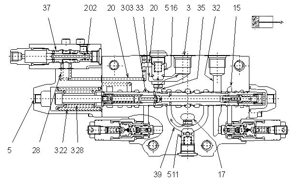
When raising the boom with a low-operating speed, the low pilot pressure presses against both boom 1 spool (303) and boom 2 spool (306). See Figure 3-117 and Figure 3-118.
The pre-load force of spring (322) and spring (328) of boom 1 spool (303) is less than the pre-load force of spring (322) and spring (323) of arm 2 spool (308). When pilot pressure is low, boom 1 spool (303) shifts and boom 2 spool (308) remains in the neutral position. See Figure 3-117, Figure 3118 and Figure 3-125 on page126.
Only hydraulic fluid from front pump (27) flows into the head side of boom cylinder (1). See Figure 3-116 on page121.
During this fine metering operation, boom raising can be controlled properly at slow speed.
Pilot pressure required to move the spool:
Section Boom 1: 87-102 psi (6-7 bar)
Section Boom 2: 174-189 psi (12-13 bar)
For a larger view of Figure 3-118, see Figure 3-115 on page121.
Figure 3-119 Lowering the Boom
While lowering the boom, pilot pressure from pilot control valve (25) flows through port (23) and shifts boom 1 spool (303) to the left against springs (322) and (328). See Figure 3-117 on page122, Figure 3-119, and Figure 3-120.
Pilot pressure flows into pilot port (21) of boom lock valve (202, 516) and shifts spool (202). Boom 1 spool (303) center bypass (33) slightly opens. See Figure 3-119.
Front pump (27) hydraulic fluid flows through center bypass (13), center bypass (11) and line (26). The hydraulic fluid pressurizes the front pump regulator’s negative control pressure, decreasing the discharge from front pump (27). See Figure 3-119 and Figure 3-120.
Front pump (27) hydraulic fluid from parallel path (17) flows through load check valve (511), path (46), and into port (4). Hydraulic fluid then flows through line (7) (not shown) and into the rod side of boom cylinder (1). See Figure 3-119 and Figure 3-120.
Return flow from the head side of boom cylinder (1) flows through line (6) (not shown), port (3), and into boom 1 spool (303). Within boom lock valve (516), pilot pressure from port (21) operates spool (202), and spool (202) forces the return flow through path (20) and into drain port (22). The pressure within the upper side of boom lock valve (516) decreases and the return flow from line (3) flows into path (16). This return flow forces open boom lock valve (516). See Figure 3-119 and Figure 3-120.
Return flow lowers the boom cylinder by flowing through path (31), return path (15) and into the tank. See Figure 3-119.
Return flow in path (45) decreases, and the boom cylinder lowers at the speed suitable to the front pump discharge. See Figure 3-119.


