
1 minute read
ME12002HYDRAULICSYSTEM


RemovingDriveShafts
1.Use plastic-headed hammer to tap lightly on the external shaft end of drive shafts (111). See Figure 3-38 and Figure 3-48.
2.Extract each drive shaft (111) from swash plate support (251). If necessary, extract rolling bearing (123), bearing spacer (127), and snap ring (824) from each drive shaft (111). See Figure 3-38 and Figure 3-48.
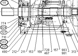
3.Complete steps 1-2 for both the rear and front pumps.
IMPORTANT:Do not re-use the extracted bearings.
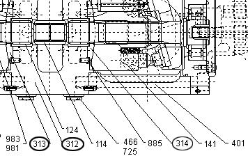
1.Remove valve plates (313, 314) from valve block (312). These may have been removed while completing the steps in “Removing all Plugs, Regulator, and Gear Pump” on page86. See Figure 3-50 and Figure 3-51.
2.Remove stopper (L) (534), stopper (S) (535), servo piston (532), and tilting pin (531) from pump casing. See Figure 3-50 and Figure 3-52.
IMPORTANT:Use a protection shield to prevent the pin head from being damaged when removing tilting pin (531). See Figure 3-52.


