1 minute read
ME12002HYDRAULICSYSTEM


AssemblingtheHydraulicPump
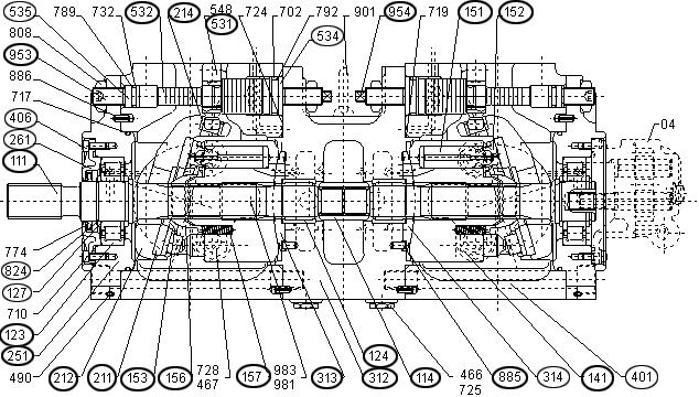
Refer to Figure 3-56 for component identification for all “Assembling the Hydraulic Pump” steps.
InstallingtheServoPump
2.Apply adhesive (medium or equivalent) to the threaded section of tilting pin (531) and servo piston (532). Allow sufficient time for the adhesive to set. See Figure 3-56 and Figure 358.
1.Install servo piston (532), tilting pin (531), stopper (L) (534) and stopper (S) (535) onto pump casing. See Figure 3-56 and Figure 3-58.
IMPORTANT:Use a protector to prevent the tilting pin head and feedback pin from being damaged while tightening servo piston (532) and tilting pin (531) onto pump casing.
3.Use plastic-headed hammer to tap lightly onto swash plate support (251), to install it onto pump casing (271). See Figure 3-58.
4.Complete steps 1-3 for both the rear and front pumps.


