1 minute read
HYDRAULICSYSTEMME12002


HydraulicPumpRotationGroup
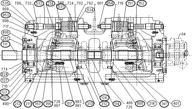
NOTICE:The hydraulic pump is symmetrical, for illustration purposes each part number is shown in Figure 3-19 only once. However, each part shown is also located on the other side of the hydraulic pump at the parallel location.
Rotation group consists of the following parts. See Figure 3-19 for identification.
Drive shaft(111)
Cylinder block(141)
Pistons (9 qty.)(151)
Shoes (9 qty.)(152)
Setting plate(153)
Spherical bushing(156)
Cylinder springs(157)
Bearings(123 & 124)
Bearings (123 & 124) support drive shaft (111) at both ends. A splined (grooved) section connects drive shaft (111) to cylinder block (141). See Figure 3-19.
Shoes (152) are shaped over the spherical end of pistons (151), forming a spherical ball joint. The shoe’s hydrostatic pocket counterbalances the pistons’ pressure hydraulic thrust, allowing the shoes
(152) to lightly slide against shoe plate (211). See Figure 3-19.
Cylinder springs (157) press pistons (151) and shoes (152) against shoe plate (211), and through setting plate (153) and spherical bushing (156). Cylinder springs (157) then press cylinder block (141) against valve plate (313). See Figure 3-19.
SwashPlateGroup
Swash plate group consists of the following parts. See Figure 3-19 for identification.
Shoe plate(211)
Swash plate(212)
Swash plate bearings(251)
Tilt bushing(214)
Tilting pin(531)
Servo piston(532)
Swash plate (212) is a cylindrical plate located next to shoe plate (211). Swash plate bearings (251) support swash plate (212). See Figure 3-19.
Tilt bushing (214) is inserted into swash plate (212). The spherical portion of tilting pin (531), pre-assembled to servo piston (532), is inserted


