1 minute read
ME12002HYDRAULICSYSTEM


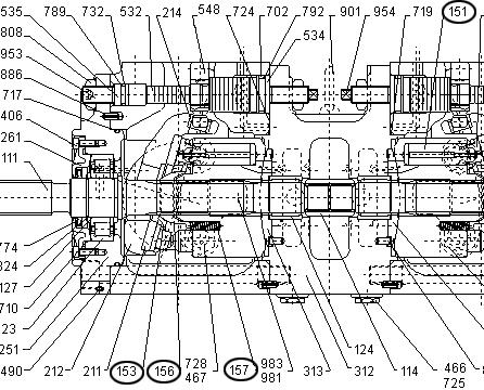
9.Place pump horizontally onto the work area with the regulator-mounting surface facing downward. See Figure 3-38 and Figure 3-40.
10.Remove the hexagon socket head bolts (401) and separate pump casing from valve block (312) on both the rear and front pumps. See Figure 3-40.
1.Remove cylinder (141) out of the pump casing (271), lifting it over drive shaft (111). See Figure 3-41.
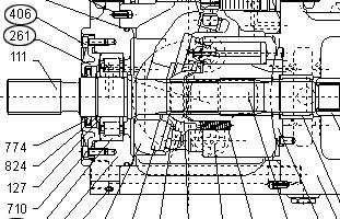
1.Remove the hexagon socket head bolts (406) and remove the seal cover (front) (261). See Figure 3-43 and Figure 3-44.
2.Remove the seal cover by fitting a bolt into the “pulling-out” tapped hole.
IMPORTANT:Do not damage the oil shaft seal installed in the cover.
3.If installed, remove the gear pump before working on the pump unit.
2.Remove pistons (151), set plate (153), spherical bushing (156) and cylinder springs (157).
See Figure 3-42.
IMPORTANT:Do not damage the cylinder, spherical bush, shoes, swash plate (212), etc. sliding surfaces.
3.Complete steps 1 and 2 for both the rear and front pumps.
4.Remove the rear pump hexagon socket headed bolts, seal cover (rear) (261), and rear cover. See Figure 3-44.


