1 minute read
ME12002HYDRAULICSYSTEM


InstallingtheOilSeal
1.Apply three bond (kk\1211” - white color) on outer surface of shaft seal (24). See Figure 3288.
2.Using seal press insertion socket, secure shaft seal (24) into housing (22). See Figure 3-288.
1.Secure pads with height 30-50 mm under the bottom of housing (22). When installing cylinder drum (16), the shaft from cylinder drum (16) extends beyond the end of housing (22).
2.Lubricate shaft seal (24) with grease. See Figure 3-288.
3.Carefully install cylinder drum (16) into housing (22). See Figure 3-290.
IMPORTANT:Do not damage shaft seal (24) when installing the shaft of cylinder drum (16).
4.Check that locking ring (17) is held in place by the probe portion of piston centering plate (19).
5.Check that the end surface of cylinder drum (16) is about 7.5 mm lower than the top of housing (22). See Figure 3-290.
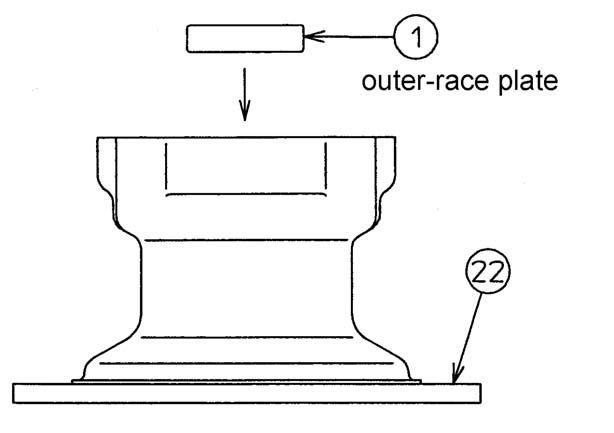
3.Install outer-race plate of taper roller bearing (1) into housing (22). See Figure 3-289.
InstallingtheCylinderDrum recommended to manually push piston (15) horizontally.
6.Assemble lining plate (5) to friction plate (4). Apply hydraulic oil to each side. See Figure 3291.
IMPORTANT:Be sure to assemble lining plate (5) to friction plate (4) in the correct sequence.
7.Install O-ring (6) into housing (22). Install Oring (7) into piston (15). See Figure 3-292.
8.Lubricate O-ring (6) and O-ring (7) with grease. See Figure 3-292.
1.Lubricate specified hydraulic oil onto the outer silding face of piston (15) and assemble the brake piston onto housing (22). See Figure 3293.
NOTICE:It is too tight to assemble piston (15) because O-rings (6,7) are fitted, therefore it is
2.Install springs (14) into piston (15). See Figure 3-294.
NOTICE:Install springs (14) into position written down during step 8 of “Removing the Balance Plate” on page191. See Figure 3-294.
3.Install spring (11) and bushing (12) with Teflon ring (13) into the bushing hole of A - B ports (30). See Figure 3-295.
4.Install control disk (9) onto A - B ports (30). See Figure 3-295.
NOTICE:Be sure control disk (9) is assembled in the correct direction. See step 3 of “Removing the Balance Plate” on page191.

6.Assemble O-ring (8) to A - B ports (30). See Figure 3-297.
7.Lubricate O-ring (8) with grease. See Figure 3297.
5.Install the inner-race plate of needle bearing (3) and locking ring (2) onto A - B ports (30). See Figure 3-296.
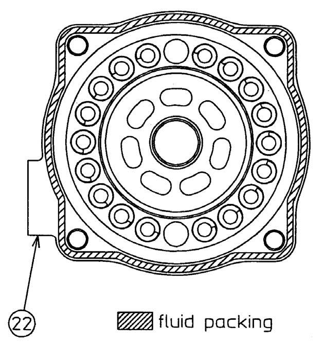
8.Apply white color fluid packing (kk\1211”white color) as shown. See Figure 3-298.