3 minute read
ME12002HYDRAULICSYSTEM


AssemblingtheCovers
1.Assemble spool covers and lock valve selector to the non-spring assembly end of the spool.
2.Using a 8 mm hexagon wrench, tighten the hexagonal socket head bolts to tightening torque 18.0 ~ 21.7 lb.-ft. (24.5 ~ 29.4 Nm).
3.Confirm that O-rings are installed.
4.Assemble spring covers and lock valve selector to the spring end of the spools.
5.Using a 8 mm hexagon wrench, tighten the hexagonal socket head bolts to tightening torque 18.0 ~ 21.7 lb.-ft. (24.5 ~ 29.4 Nm).
6.Confirm that O-rings are installed.
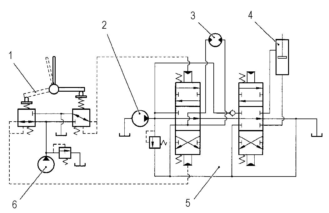
HydraulicPilotingSystem
1Pilot control valve
2Variable pump
3Hydraulic motor
4Hydraulic cylinder
5Main valve block
6Fixed displacment pump
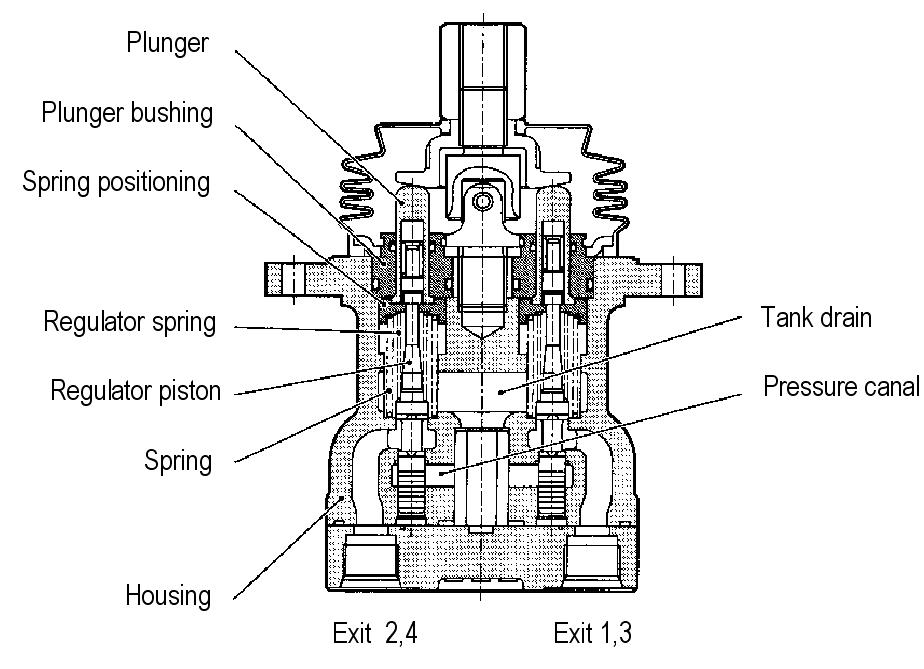
RightJoystickPorts
Exit 1Bucket cylinder extending Exit 2Boom cylinder retracting
Exit 3Bucket cylinder retracting Exit 4Boom cylinder extending
DisassemblingtheJoystick
NOTICE:These steps apply to both the right and left joystick.
1.Remove the pilot conrol valve.
2.Disconnect all ports.
3.Remove the fixing pin from the joystick base. See Figure 3-175.
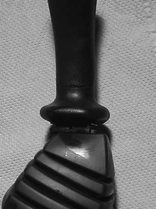
Removethefixingpinfromthe joystickbase
Exit 1Swing motor left
Exit 2Dipper arm cylinder retracting
Exit 3Swing motor right
Exit 4Dipper arm cylinder extending
Hydraulicsystemme12002
4.Remove handle. See Figure 3-175.
8.Rinse the pilot valve in an alkane-based kerosene oil. See Figure 3-178.

9.Install blind plugs into all ports.
Warning
ITEMSUNDERTENSION:Returnspring(221), plate(151)andpushrod(212)areundertensionwhenjoint(301)loosens.Besurethat thesepartsdonotlaunchfromtheunit, becausethismaycausedamageand/orserious injury.Weareyeprotection.
IMPORTANT:Do not damage the
12.Remove plate (151). See Figure 3-181.
Warning
ITEMSUNDERTENSION:Returnspring(221) releaseswhenremovingplug(211).Besure spring(221)doesnotlaunchfromtheunit, becausethismaycausedamageand/orserious injury.Weareyeprotection.
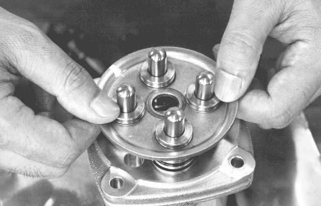
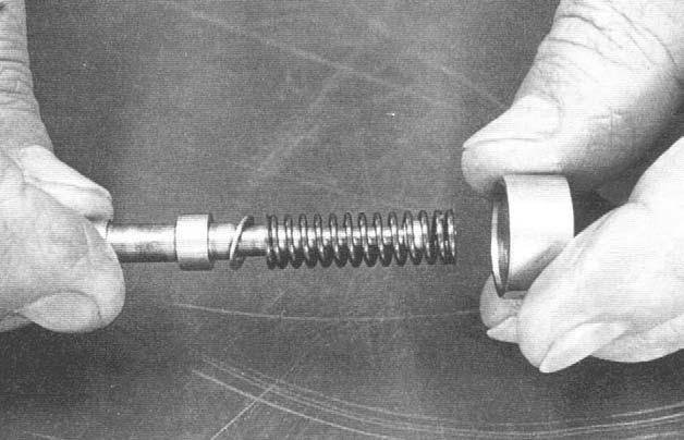
14.Remove push rods (212), plugs (211), reduction valve assembly and return springs (221) from casing (101). See Figure 3-183.

15.Write down the correct order and retain these parts in the correct order for re-installing the parts into casing (101).
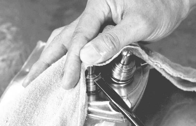
13.When return spring (221) is weak, plug (211) is held into casing (101) by O-ring friction. Release the friction using a screwdriver as shown.
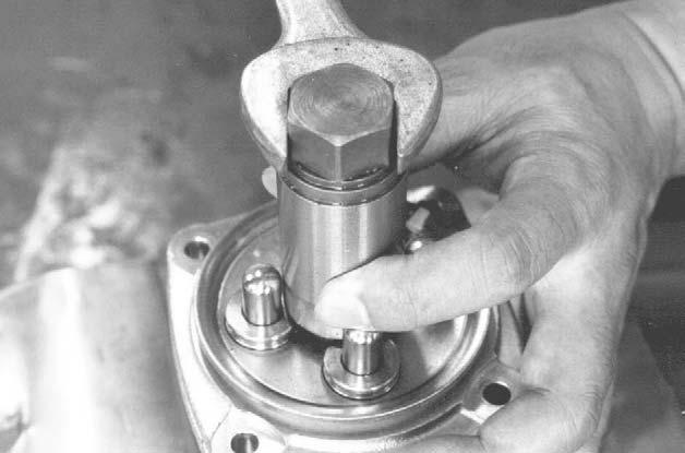
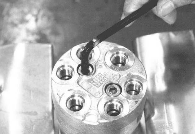
16.If necessary, re-secure the pilot valve into the vice so that port plate (111) is positioned at the top, as shown. See Figure 3-184.
17.Using an Allen wrench, loosen hexagon bolts M8 (125) as shown. See Figure 3-184.
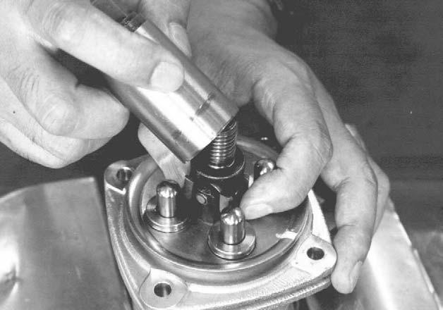
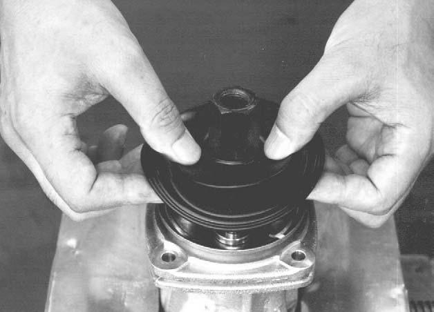
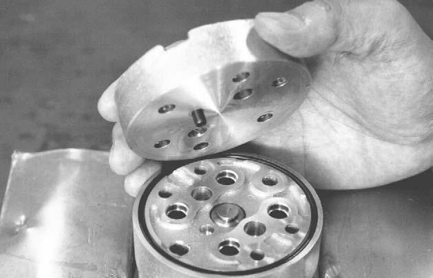
18.Remove port plate (111) and O-ring (122) from casing (101). See Figure 3-185.
19.Remove bushing (131) from casing (101). See Figure 3-185.
IMPORTANT:The surface of spool (201) and spring (216) can be damaged because of mishandling. Do not damage the surface of spool (201) while removing spool (201) and do not push spring (216) seating downward more than 0.2” (6 mm).
22.Disassemble spool (201), spring seating (216), secondary pressure spring (241) and washer #2 (217) as shown. See Figure 3-187.
23.Retain spool (201), spring seating (216), secondary pressure spring (241) and washer #2 (217) in the order of disassembly for reassembly. See Figure 3-187.
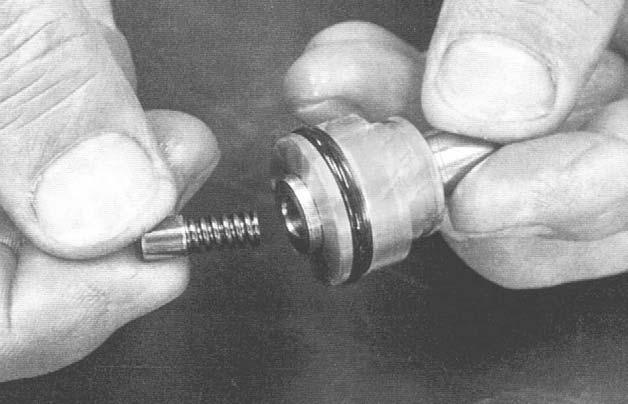
20.Disassemble the reduction valve by pressing downward on spring seating (216) and flexing secondary pressure spring (241).
21.Slide spring seating (216) sideways, and remove it from spool (201) through the larger opening. See Figure 3-186.
24.Remove secondary spring (246) and spring seating (218) from push rod (212). See Figure 3-188.
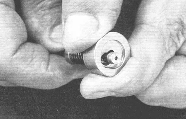
25.Remove push-rod (212) from plug (211). See Figure 3-189.
Be sure to carefully monitor the quality of the alkane-based kerosene oil (or similar cleaning fluid).
IMPORTANT:Dirty alkane-based kerosene oil can damage the parts, and cause a deterioration in performance after reassembly.
6.Place the parts into the “finish wash” container.
7.Rotate the container slowly until even the inner areas of the parts are clean.
8.Remove the parts from the finish wash container.
9.Using a clean cloth, wipe any remaining alkane-based kerosene oil (or similar cleaning fluid) off of the parts.
10.Using the other clean cloth, dry the parts.
IMPORTANT:Do not use compressed air for drying the parts because dust and moisture in the compressed air may damage the parts and cause corrosion.
IMPORTANT:Be sure to dry the parts immediately after cleaning and do not leave them un-dried and standing because they may begin to corrode and performance after reassembly will be impaired.
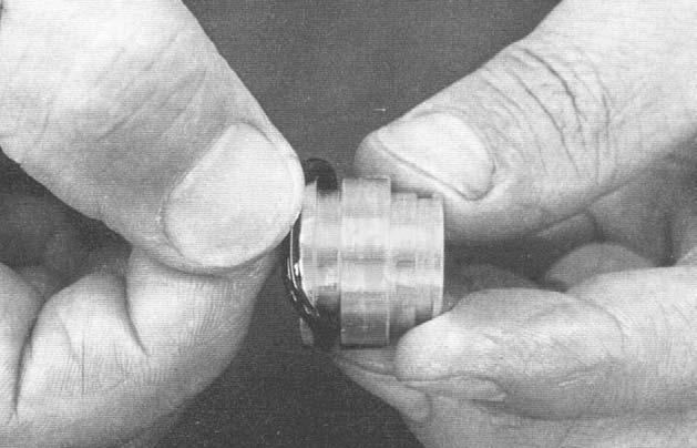
26.Remove O-ring (214) from plug (211). See Figure 3-190.
27.Using a small screwdriver, remove seal (213) from plug (211).
CleaningtheParts
1.Obtain two containers large enough to submerge each individual part and two clean cloths. The “finish wash” container is rotated in step 7.
2.Fill both containers with alkane-based kerosene oil (or similar cleaning fluid).
3.Wash all parts in one of the containers.
4.Reduce the risk of damaging dirty parts covered with dirt and oil by submerging and soaking the individual parts thoroughly until the dirt and oil float to the cleaning fluid surface.
5.Replace the alkane-based kerosene oil (or similar cleaning fluid) if it becomes visibly dirty.
PreventingPartCorrosion
1.Coat the parts with an anti-corrosion spray, according to the manufacturer’s specifications.


