JOHN DEERE ENGINE 4045TF270 (SN AC02633 AND UP) 3. Turn the radiator cap to the notch to release the pressure.
ME12002 E
4. Remove the radiator cap.
D
5. Remove exhaust elbow (A) at the air intake. See Figure 4-8.
NOTICE: The cylinder head is removed more easily if you remove the turbocharger without removing the exhaust bracket. 6. Disconnect the oil outlet and intake lines (B) from turbocharger (C). See Figure 4-8. 7. Remove turbocharger (C) and exhaust elbow (A). See Figure 4-8.
Figure 4-10 Fuel Filter/Water Seperator
IMPORTANT:Always replace the cylinder
4. Remove fuel filter/water seperator (E) and the brackets if necessary. See Figure 4-10.
head cover gasket if the cylinder head cover is removed when overhauling the engine or cylinder head. 8. Remove and retain the hexagon nuts and Orings from the cylinder head cover (D). Replace them if necessary. See Figure 4-8. 9. Remove the cylinder head cover (D). See Figure 4-8. Removing the Fuel Lines, Fuel Filter/Water Separator A
C
3. Remove the fuel lines.
5. If installed, remove fuel pump (D). Check the front surface of the pump lever for wear. Replace the fuel pump if the surface is flat or concaved due to wear. See Figure 4-10. 6. (Optional) Remove the alternator to ease the work. 7. Remove the tube that connects the thermostat housing with coolant pump (C). See Figure 49. 8. Remove fuel return line (F) and fuel feed lines (G) as a unit. See Figure 4-11. 9. Remove fuel injection nozzles (H). See Figure 4-11. F
G
H B
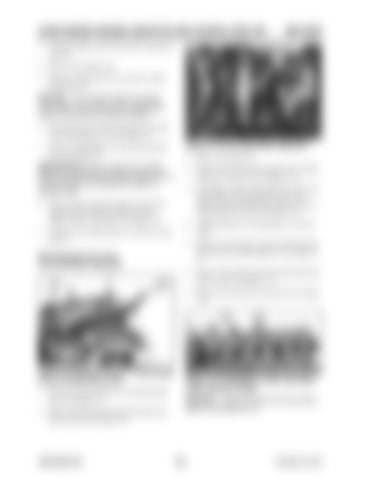
Figure 4-9 Exhaust Bracket, Turbocharger and Oil Intake/Outlet Lines 1. Remove exhaust bracket (A) using the guide pins. See Figure 4-9. 2. Remove the thermostat housing/coolant supplier unit (B). See Figure 4-9.
909768/BP1207
Figure 4-11 Fuel Return Lines, Fuel Feed Lines, Injection Nozzle
NOTICE: Loosen all rocker arm set screws before removing the unit.
208
Printed in U.S.A


