HYDRAULIC SYSTEM Assembling the Cover
ME12002 2. Using a 10 mm hexagon wrench, tighten screws (29), A - B ports (30) and housing (22) to tightening torque 76 lb.-ft. (103 Nm). See Figure 3-300. Assembling the Relief Valve
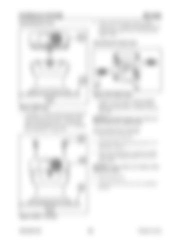
Figure 3-301 Relief Valve
Figure 3-299 Cover 1. Assemble A - B ports (30) and control disk (9) to housing (22), line-up the matching marks made on housing (22) and A - B ports (30) before disassembling. See step 1 of “Marking the Swing Motor” on page 190.
1. Using a 27 mm wrench, install and tighten bypass valve (26) onto A - B ports (30) to tightening torque 29 lb.-ft. (39 Nm). See Figure 3-301.
NOTICE:Assemble bypass valve (26) to its original state when reassembling. Checking Relief Valve Assembly
1. Open inlet and outlet port. 2. Load pilot brake release port pressure to 3-5 MPa (435-725 psi). 3. Check that output shaft is rotating smoothly with a torque of approximately 15-21 lb.-ft. (20-29 Nm).
NOTICE:If output shaft is not rotating, disassemble and check. 4. Open the drain port. 5. Check that relief valves are set to regulation pressure.
Figure 3-300 A - B Ports
909768/BP1207
200
Printed in U.S.A


