ME12002
HYDRAULIC SYSTEM
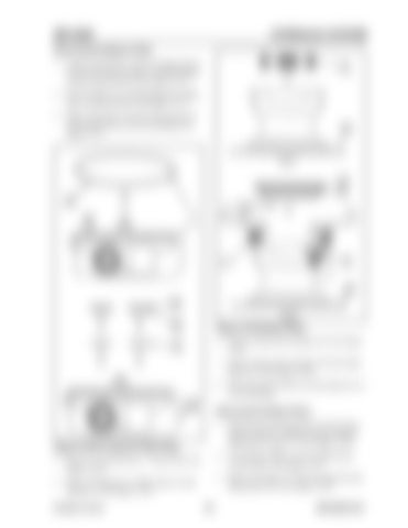
Removing the Balance Plate 1. Using a steel pointer, remove locking ring (2), remove the inner-race plate of needle bearing (3) and control disk (9). See Figure 3-277. 2. Work carefully to avoid damaging the sliding face of control disk (9). See Figure 3-277. 3. Before removing, write down the location of control disk (9) for correct assembling. See Figure 3-277.
Figure 3-279 Brake Piston 6. Remove brake piston springs (14). See Figure 3-279. 7. Remove brake piston springs (14) from brake piston (15). See Figure 3-279. 8. Write down the position of each spring for correct assembling. Removing the Brake Piston 1. When removing brake piston (15) from housing (22), there is a sliding resistance against tightening O-rings (6, 7). See Figure 3-279.
Figure 3-278 O-ring and Teflon Ring
2. Use tap holes (M6) to remove brake piston (15) as shown. See Figure 3-279.
4. Remove O-ring (8) from A - B ports (30). See Figure 3-278.
3. Remove O-rings (6, 7) from housing (22) and brake piston (15). See Figure 3-279.
5. Remove bushing (12), Teflon rings (13) and spring (11). See Figure 3-278. Printed in U.S.A
191
909768/BP1207


