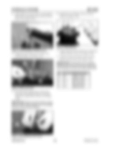
HYDRAULIC SYSTEM 27. Apply adhesive (Loctite #241 or equivalent) to the surfaces of hexagon socket screws (472) as shown. See Figure 3-258.
ME12002 30. Install the top of bellows (501) into block (420). See Figure 3-261.
472
Figure 3-262 Bellows Figure 3-259 Hexagon Socket Screw 28. Tighten hexagon socket screw (472) to the specified torque. See Figure 3-259.
31. Apply anticorrosion oil (WD-40 or equivalent) inside of bellows (501). See Figure 3-262. 32. Install the bottom of bellows (501) into the groove in cover (201). See Figure 3-261.
IMPORTANT:If the bellows are not tightly
420
installed into the groove (and are loose), bellows resistance to dust and water decreases. No. 125 301 312
Figure 3-260 Push Rod
Screw size Tightening torque 15.2±1.1 Lb.-Ft. M8 (20.6±1.5 Nm) 34.7±2.1 Lb.-Ft. M14 (47.1±2.9 Nm) 50.7±3.6 Lb.-Ft. M14 (68.8±4.9 Nm)
29. Tilt block (420), apply grease to the top of push rod (214) and inject grease into grease cap (203) of plug (202) as shown. See Figure 3-260.
IMPORTANT:Apply and inject grease using a spatula made of soft material. Do not damage the push rod and plug surfaces. 501
201
Figure 3-261 Bellows and Cover 909768/BP1207
180
Printed in U.S.A


