ME12002
HYDRAULIC SYSTEM
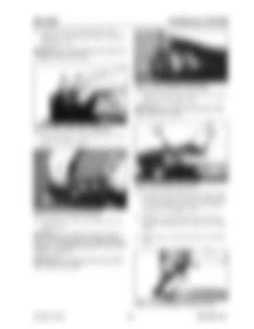
20. Position a socket onto bushing (414) and lightly tap it with a hammer until it is installed. See Figure 3-253.
NOTICE:Be sure that bushing (414) does not dislodge inside cover (201). 271
Figure 3-256 Hexagon Socket Bolt 23. Tighten hexagon socket bolt (271) to the specified torque. See Figure 3-256.
NOTICE:Be sure that damping spring (336) does not lift cover (201). Figure 3-254 Lower Cover Assembly
420
21. Secure the lower cover assembly into a vice as shown. See Figure 3-254.
201
201
413
Figure 3-257 Block and Cover 24. Assemble block (420) onto cover (201), and in the same position as written down during step 8 of “Disassembling the Pilot Control Pedal” on page 171. See Figure 3-257.
102
Figure 3-255 Cover and Casing
25. Manually press downward onto block (420) and insert camshaft (413) as shown. See Figure 3-257.
22. Assemble cover (201) onto casing (102). See Figure 3-255.
NOTICE:Be sure that the parts are assem-
26. Apply grease to the bearing parts of camshaft (413).
bled in the same position as written down during step 11 of “Disassembling the Pilot Control Pedal” on page 171.
NOTICE:Be sure that damping spring (336) does not lift cover (201). 472
Figure 3-258 Hexagon Socket Screws Printed in U.S.A
179
909768/BP1207


