HYDRAULIC SYSTEM 12. Install piston (224) into casing (102) as shown, and in the same position as written down during step 19 of “Disassembling the Pilot Control Pedal” on page 171.
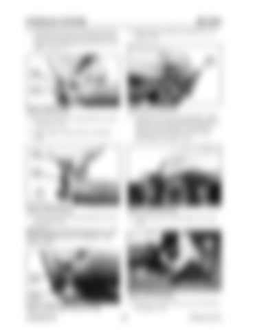
ME12002 16. Install grease cap (203) into plug (202). See Figure 3-250.
214
202
202
212
Figure 3-248 O-ring
Figure 3-251 Push Rod
13. Install O-ring (212) onto plug (202) as shown. See Figure 3-248.
17. Install push rod (214) into plug (202). Apply working oil to surfaces before fitting push rod. There is a risk of damage to the rib part of packing (210); do not use excessive force when fitting. See Figure 3-251.
14. Apply a light coating of grease to packing (210).
210
202 102
Figure 3-249 Packing
Figure 3-252 Push Rod
15. Install packing (210) into plug (202) as shown. See Figure 3-249.
18. Install the push rod subassembly into casing (102).
NOTICE:Be sure that packing (210) is in the correct orientation prior to installation. See Figure 3-249.
201
414 203
202
Figure 3-250 Grease Cap and Plug 909768/BP1207
Figure 3-253 Bushing 19. Position cover (201) onto a level work surface. See Figure 3-253. 178
Printed in U.S.A


