ME12002
HYDRAULIC SYSTEM
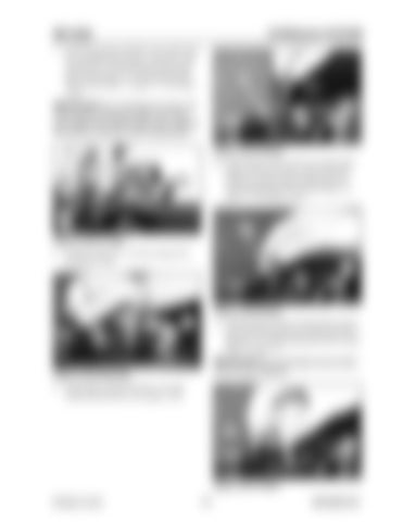
7. Install the pressure reduction valve sub-assembly, assembled during steps 1 through 6, into casing (101), in the same position as written down during step 27 of “Disassembling the Pilot Control Pedal” on page 171. See Figure 3-242.
218
IMPORTANT:Do not damage the lower end
102
of the spool by hitting the lower end of the spool against the casing edge when installing the pressure reduction valve subassembly. Figure 3-245 Washer 10. Install spring washer (218) into casing (102), using a tweezers as shown, and in the same position as written down during step 23 of “Disassembling the Pilot Control Pedal” on page 171. See Figure 3-245.
213 211
101
336
Figure 3-243 O-rings 8. Install O-rings (211, 213) into casing (101). See Figure 3-243.
102
Figure 3-246 Spring 225
102
11. Install spring (336) into casing (102) as shown, and in the same position as written down during step 21 of “Disassembling the Pilot Control Pedal” on page 171.
IMPORTANT:Do not damage spring washer (218) during installation.
Figure 3-244 Steel Ball 9. Install upper casing (102) into a vice and install steel ball (225). See Figure 3-244.
224 102
Figure 3-247 Piston Printed in U.S.A
177
909768/BP1207


