HYDRAULIC SYSTEM
ME12002
Hydraulic Pedals
Return spring (335) presses spool (301) against push rod (214).
General Information
Tilting the control handle presses down push rod (214) and spring seat (311), changing the setting of the secondary pressure setting spring (324).
The PVD6P valve is a remote control pressure reduction valve equipped with a shock absorber. A set of four pressure reduction valves, used for controlling the secondary pressure, are installed in a single valve casing.
Port P, oil inlet (primary pressure) and port T outlet (tank) are in casing (101).
Moving the control lever adjusts the output pressure. The control lever valve casing contains a damping component to prevent engine rpm fluctuation. Specifications Primary pressure Secondary pressure Permissible back pressure Nominal flow Control angles Weight Piping
Maximum pressure 994 psi (69 bar) 0~638 psi (0~44 bar) (maximum control pressure) Maximum 435 psi (30 bar)
3 gpm (10 L/min) ±10°, ±12.4° (single) 9 lbs. (4 kg) Use a supply pipe approximately 8mm internal diameter and a maximum of 10 ft. (3 m) in length. Return oil should flow directly into the tank to avoid back-pressure.
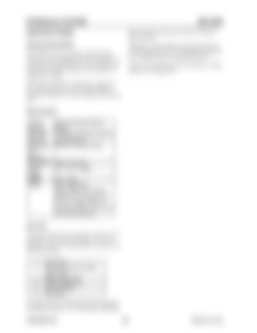
Structure The remote control valve structure is shown in the assembly cross-section. See Figure 3-212. The reduction valves are inserted into the vertical axial hole in the casing. 1 2 3 4 5 6
Spool (301) Secondary pressure setting spring (324) Return spring (335) Spring seating (311) Push rod (214) Plug (202)
Secondary pressure setting spring (324) calculates secondary pressure as 73~145 psi (500~1000 kPa). 909768/BP1207
166
Printed in U.S.A


