HYDRAULIC SYSTEM
ME12002
Assembling the Joystick
3. Write down the fitting position so that spring pin (126) can be inserted into the casing opening.
111
4. Tighten hexagon bolt M8 (125) to tightening torque 15.2±1.1 lb.-ft. (20.6±1.5 Nm). See Figure 3-193. 131
IMPORTANT:The surface of spool (201) and 101
122
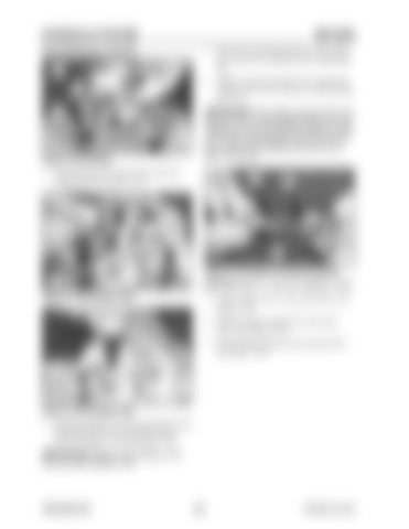
Figure 3-191 Casing
spring (216) can be damaged because of mishandling. Do not damage the surface of spool (201) while removing spool (201) and do not push spring (216) seating downward more than 1/4” (6 mm).
1. Install bushing (131) and O-ring (122) into casing (101). See Figure 3-191.
216
217
241
201
125
Figure 3-194 Spool and Spring Seating 111
Figure 3-192 Hexagon Bolt
NOTICE:Steps 5-7 must be installed in order. 5. Install washer #2 (217) onto spool (201). See Figure 3-194. 6. Install secondary spring (241) onto spool (201). See Figure 3-194. 7. Install spring seating (216) onto spool (201). See Figure 3-194.
111
Figure 3-193 Hexagon Bolt 2. Install port plate (111) onto casing (101) using hexagon bolts M8 (125) and seal washers (121). See Figure 3-192 and Figure 3-193.
IMPORTANT:Replace seal washers (121) with new seal washers (121).
909768/BP1207
160
Printed in U.S.A


