ME12002
HYDRAULIC SYSTEM
Disassembling and Assembling the Control Valve
Tools Prepare the following tools before disassembling the control valve.
General Information
Name of tool Vice mounted on bench (soft jaws) Hexagon wrench Socket wrench Spanner Adhesive (Loctite #262)
1. Prepare fresh cleaning oil, hydraulic oil, grease, etc. 2. Prepare the hydraulic test equipment and tools (test for the relief characteristics, leakage, flow resistance, etc.). See “Tools” on page 147. 3. All hydraulic pump components are manufactured with precision. Thoroughly clean the work area before disassembling and/or reassembling the pump.
Quantity
Size (mm)
1 unit Each 1 piece Each 1 piece Each 1 piece
8, 10 and 12 27 and 32 27, 32, 41
1 piece
Disassembling the Control Valve
4. Spread rubber sheet, cloth, paper, or similar material to cover the work area.
Place Control Valve in Work Area
5. Be sure dust, sand, debris, etc. do not enter the pump control valve.
in a clean and dry environment and do not damage the sealing flange faces.
IMPORTANT:Disassemble the control valve
6. Remove the control valve from the excavator.
Disassembling of Main Spool (except straight travel)
7. Attach caps and masking seals to all control valve ports. 8. Clean the outside of the control valve and be sure that the caps and masking seals are attached properly. 9. Carefully support the body section of the casing when carrying or transferring the control valve.
IMPORTANT:Do not lift the control valve by lifting the exposed spool, end cover section, etc. 10. Disassemble the pump on rubber sheet, cloth, paper, or similar material used to cover the work area. See step 4.
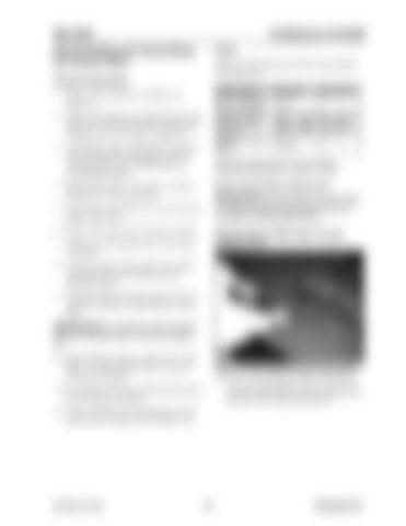
Figure 3-158 Hexagon Socket Head Bolts 1. Using a 8 mm hexagon wrench, loosen hexagon socket head bolts and remove spring cover, and lock valve selector (for boom1).
11. Do not disassemble any component that cannot be tested after re-assembly. 12. After re-assembly, test components for relief characteristics, leakage, flow resistance, etc.
Printed in U.S.A
147
909768/BP1207


