ME12002
HYDRAULIC SYSTEM
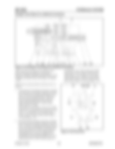
Straight Travel Spool (no additional actuation)
Figure 3-152 Straight Travel Spool (no additional actuation) swing (309), arm1 (302) and boom2 (306). See Figure 3-118 on page 122 for boom2 (306), Figure 3-151 on page 142 for travel right spool (301R), spools of swing (309), arm1 (302), Figure 3-152 and Figure 3-153.
When only the travel spools are operated, pilot path (18) and spool chamber (13) pressure decreases. Spring (324) and spring (325) then shift straight travel spool (305) to the right. See Figure 3-152. Front and rear pump hydraulic fluid then flows as follows: 1. Front pump (27) hydraulic fluid flows through line (30), port (10), and then separates into two flows. One flows through center bypass (15) and into travel left spool (301L). The other flows through parallel path (24) and into option spool (310), boom 1 (303), bucket (304), and arm 2 (308). See Figure 3-143 on page 136 for arm 2 (308), Figure 3-146 on page 139 for spool (310), Figure 3-151 on page 142 for travel left spool (301L), boom 1 (303), bucket (304), Figure 3152 and Figure 3-153. 2. Rear pump (28) hydraulic fluid flows through line (31), port (9), and then separates into two flows. One flows through center bypass (8) and into travel right spool (301R). The other flow opens check valve (7) to the right and flows through path (6), located in straight travel spool (305), and into parallel path (22). From parallel path (22), it flows into the spools of Printed in U.S.A
Figure 3-153 Pump Flow
143
909768/BP1207


