ME12002
HYDRAULIC SYSTEM
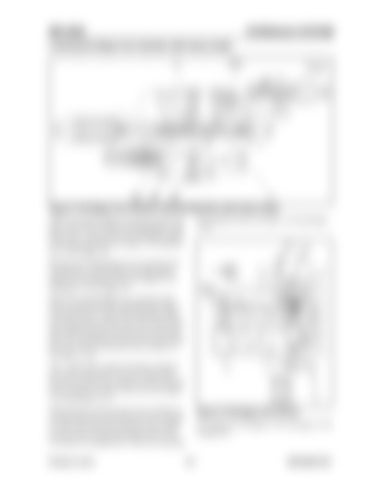
Lowering the Dipper Arm Cylinder (with heavy loads)
Figure 3-134 Dipper Arm Cylinder Lowering Operation (with heavy loads) While lowering the dipper arm, pilot pressure from pilot control valve (31) flows through path (2) and presses arm 1 spool (302) to the left against spring (322) and spring (328). See Figure 3-135 and Figure 3-130 on page 129.
(28) hydraulic fluid. See Figure 3-134 and Figure 3-135.
Pilot pressure through pilot line (2) and pilot line (6) shifts arm 2 spool (308) to the right against spring (322) and spring (329). See Figure 3-135 and Figure 3-132 on page 130. While lowering the dipper arm, hydraulic fluid from rear pump (28) flows through center bypass (10) and into arm 1 spool (302). Hydraulic fluid from front pump (27) flows into arm 2 spool (308) and combines with the total flow from rear pump (28). The combined flow proceeds into line (4) and then flows into the head side of arm cylinder (1). See Figure 3-135. Arm 1 spool (302) contains the built-in regeneration circuit using check valve (34). Return flow from the rod side of arm cylinder (1) flows through line (3) and into arm lock valve (516). See Figure 3-134 and Figure 3-135. When pressure on the rod side of arm cylinder (1) is greater than that of the head side of arm cylinder (1), return flow from the rod side of arm cylinder (1) flows into the head side through check valve (34), path (35), and path (36). This saves rear pump Printed in U.S.A
Figure 3-135 Dipper Arm Control For a larger view of Figure 3-135, see Figure 3-128 on page 128.
131
909768/BP1207


